Soooo…. I need to check the Maker Faire website more frequently. This past Sunday I was looking to see if there were any maker faires coming up at any point in the relatively near future. Only one I saw… this upcoming Sunday! It’s the Downtown Columbia Mini Maker Faire, in Columbia, Maryland. Nothing else shows up on the map in my area right now, so it’s this or nothing for a while.
Enter panic mode.
I need to network and meet others in the hobby, so I’m definitely going. I think it’d be better for conversations if I had something to show… but the only thing I had going on at the moment is the keytar project, and it’s not gonna be finished for a couple more weeks. I’m waiting on my logo decal and I need a Saturday or Sunday morning to epoxy the greeblies and let it set for most of the day outside so I don’t fill my home with fumes. Then letting it set, priming/painting, decals, and another few rounds of painting with clear layers.
Buuuut, I figured I could get it assembled (I had to quickly order some more parts) and have an early version of it on hand as a demonstration of what I do. So that’s what I’ve been busy doing.
I went ahead and remade a couple of pieces to fix a couple of things I wasn’t happy with and add a grip to grab the keyboard more easily. I also sanded and wiped down all the plastic parts I’m planning on painting, since I had already started the process.

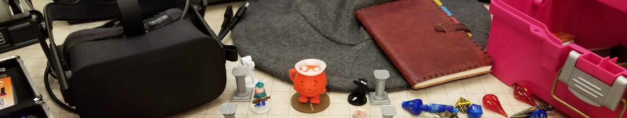
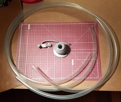
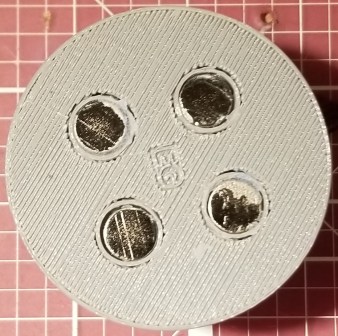
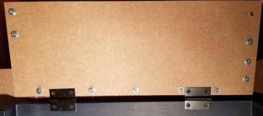
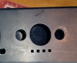
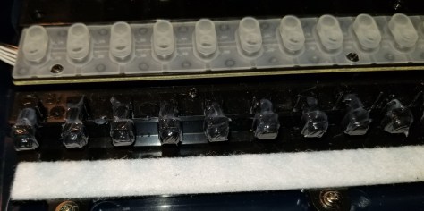
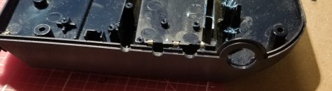
Here’s a new reference photo for the retaining nuts, by the way.

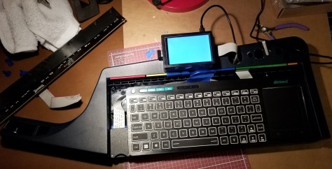
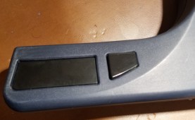
I assembled as much as I could, waiting on the other parts to come in before dealing with the inevitable cabling issues. I forgot how many little components needed to be added back in from the original keytar! I had to go tracking them down from the various containers I had put them in. I had forgotten about this thing and the button associated with it.
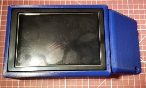
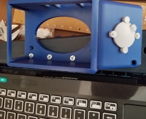
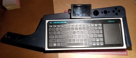
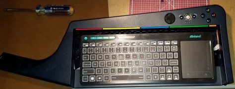
Exterior

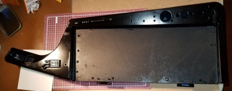
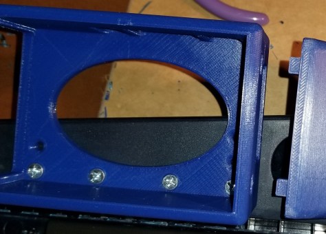
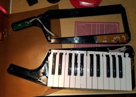
Interior
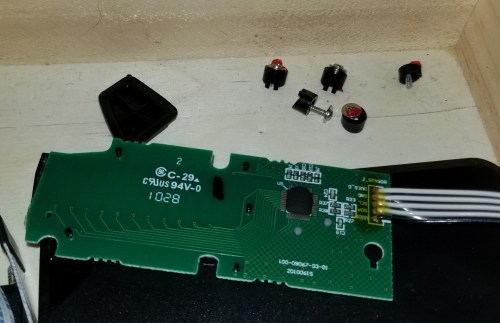
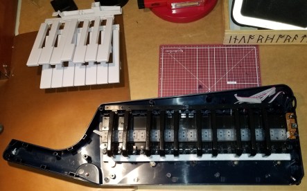
This piece right here still needed some holes drilled and unnecessary parts trimmed off.

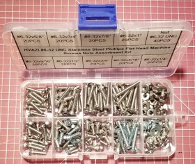
The screw assortment was a LIFESAVER! DO NOT ATTEMPT THIS SORT OF BUILD WITHOUT IT! I kept finding out that the screws that had worked previously didn’t always work the best, or interfered with changes that had been made since their original fitting.
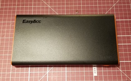
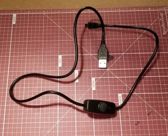
I ordered a belt amp and matching audio cable to connect to the keytar to continue the whole “decker disguised as a rocker” motif.

As some of you probably see coming, I forgot that those cables use a much larger connector.


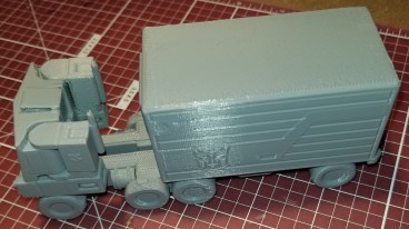
Amaz… I mean technosummoning to the rescue! I ordered an adapter. I checked to make sure it works by playing the Ghostbusters theme on my phone. Works great! Now I just have to figure out how to get comfortable with the other settings on the amp.

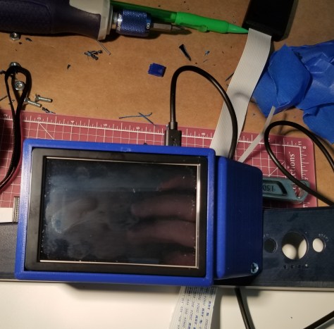
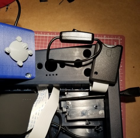
I’ve designed and printed a sleeve to interface the adapter into the case through the big hole that until now served no purpose on the case.


For now I’m using a dab of hot glue to hold it in place. I think I can remove it later for the paint job. First time I’m actually using this particular hot glue gun. Anyway, a bunch of tape, command strips, and screws later, I finished getting this assembled.

Exterior

Interior

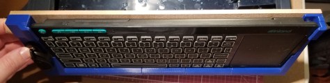
IT’S ALIVE!!!
Turns out this thing is heftier than I expected. Main thing I’m trying to figure out I’m going to carry this while walking around. It appears that the way the strap is mounted, if I just try to rotate the sling to the back the load directions change and cause the strap to slip off the knobs. This might have to ride slung under my arm this trip. Maybe later I can figure out a better way to carry it. Right now I’m just hoping it doesn’t rain, because PLA can absorb water a bit, and the case overall isn’t sealed.
Anyway, I’ve got it put together, I’ve tested it with some music on the belt amp, and I’m trying to get everything together for going to a maker faire (maker coins, additional accessories, etc). But at least I have something more to show than just claiming I do some 3D printing. I hope to meet people at the faire, make some contacts, and maybe get some suggestions on how to solve a couple issues.
In other news:
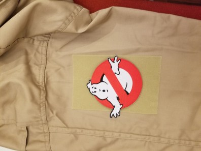
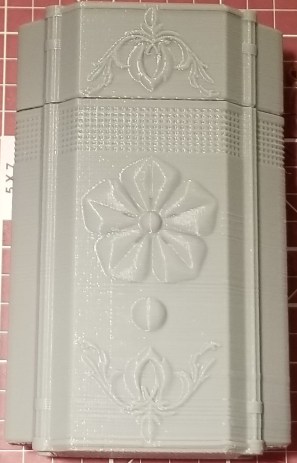
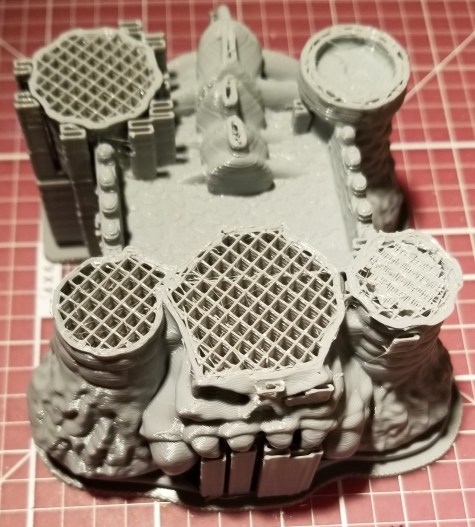
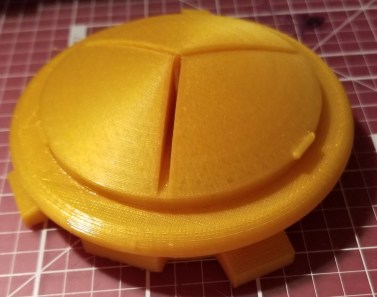
I felt I needed another thing to have on display regarding 3D printing, and since I don’t have a booth of my own it needed to also be wearable. Well… when I was thinking about it, I was watching Extreme Ghostbusters episodes, so I decided to make a miniature of the ghost trap Kylie wears on the back of her armor.
I didn’t see one on Thingiverse, so I decided to design one from scratch on Autodesk Fusion360. Then I had to do a bit of splicing of files for the twist lock and belt clip. It was supposed to come off easily for handing to people to look at, but it fits a bit too snugly and I don’t really have the time to adjust the connector.
Here’s the result:


Note, the parts for the connection are combined from other files, and they will be noted as such in the final Thingiverse entries.

So, yeah, now I have something I can have on me to hand people to look at if they have questions or want an example. And for any other Ghostbusters fans, I know some people are gonna disagree with the layout of the feet on the trap, but as an engineer looking at the reference picture I had, this is how they appeared to be laid out. Three feet and a handle spread out as if there are 4 feet.