Category Archives: Projects

Pirate Hat

I keep a wall of hats above my shelves of board games, as kind of a thematic backdrop, especially with the RPGs. One that needed to go on the wall is a pirate hat. However, most of the pirate hats I saw were disappointing to me. For one thing, ever since my childhood, this has been my idea of THE pirate hat:

Dustin Hoffman as Captain Hook in the movie Hook.

So, I decided to make my own version of the hat.
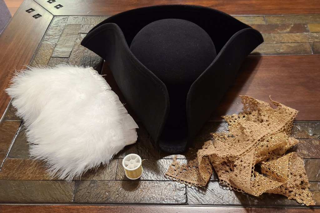
Parts list:

  • Black thread (any black thread of reasonable strength will do)
  • Felt glue (picked some up from the hobby store)

Tools List:

  • Sewing kit (extra thimbles in my case, both so I could push the needles through the material and so I didn’t accidentally stab myself as much)
  • Lots of pins
  • Disposable brush
  • Cutting pliers
  • Lint roller
  • Painter’s tape
  • Hand towel
Note: I didn’t know I needed the black felt tape yet.

To start with I took the hat, and cut and sewed the gold trim on along the edge, using the gold thread to hide the stitching.

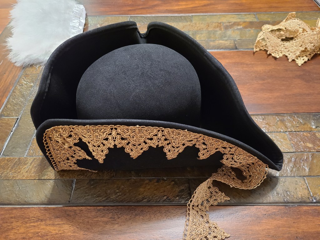
In some places where there was a bit internal curve I had to detail trim some of the lace so it would lay flat and not look too out of place.

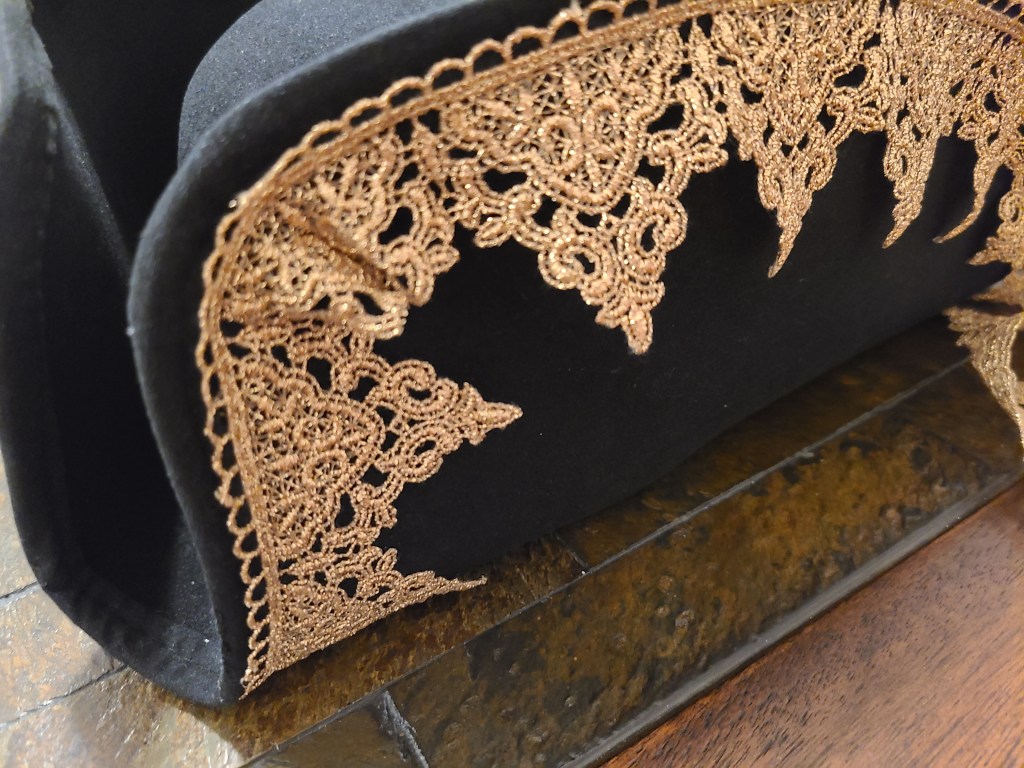
As I expected, I would see that I would need to glue and/or stitch the lace points down so they would lay right.

I started brushing on felt glue on the back of the lace, and pinning it into place so that I wouldn’t have to worry about curling or stretching or anything like that.

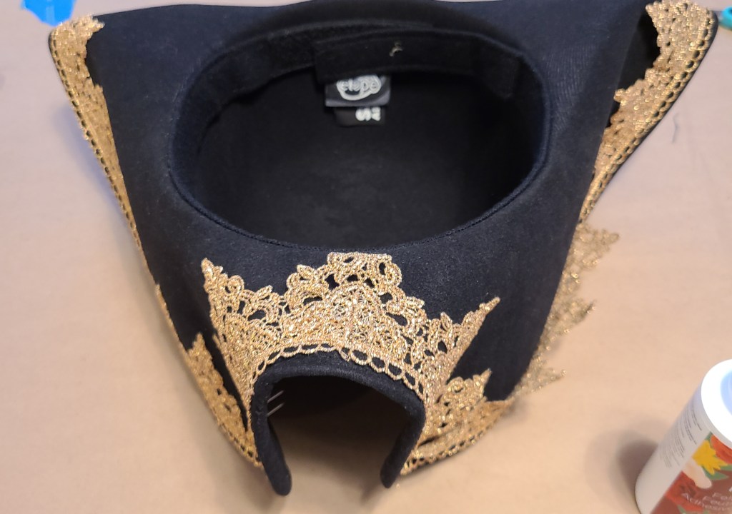
I let the glue dry for 24 hours, then removed the pins and began stitching some more. Reinforcing the points, some spots I thought were popping up a little, and other parts I thought might need more stitching. Not much to see there except some ugly stitches that I later covered up.

Upon consultation, I realized that the maribou was a bit too thick, and needed to be trimmed to work. I cut it into 3 distinct sections for easier sewing, and then used the pliers to remove alternating groups of feathers. Over time I stitched through the connecting ribbon of the maribou trim into the hat, with some truly atrocious looking stitches. You can also see some of the tack stitches that I used to reinforce the lace and glue.

Tip: when you stitch the maribou through, some adhesive from the ribbon will adhere to the needle, and tiny bits of feather will be pulled through with it. As far as I know you can’t prevent this, but just know that you will need to use your fingernails or maybe some tweezers to pluck those feather bits off. Then run a lint roller over it.

In the spirit of Adam Savage’s philosophy of “hide your costuming crimes,” I decided that the stitching was going to bother me and needed to disappear. If I were just wearing the hat on my head, I probably wasn’t going to care, but my hats hang on a wall facing the living area, so it needed to look a little better. This is when I decided to do some research, and found a black felt adhesive tape that would blend into the hat.

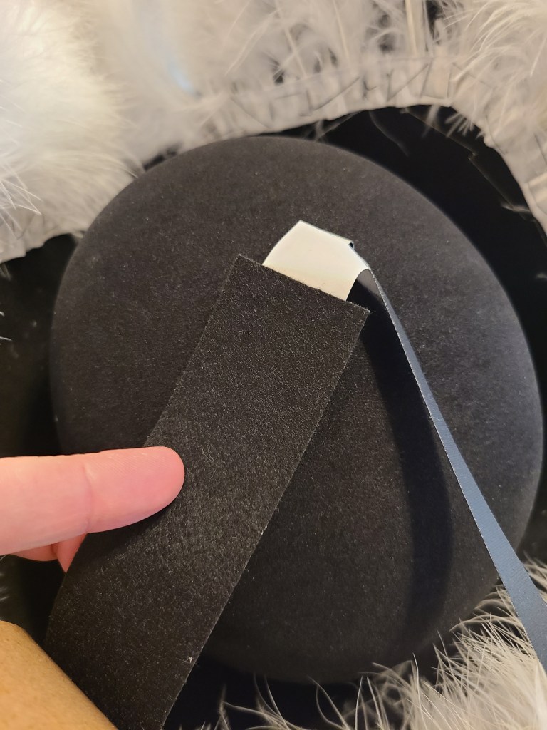
To not end up with a mess with all these light weight feathers sticking to the tape, I prepped by using a hand towel to hold the feathers back with the weight of it.

Then I cut segments of tape to handle the contours of stitching and cover things up. I placed the tape in segments, and then moved to each section in turn.

By the end of it, the stitching was pretty much hidden.

At this point, you’re going to want to use a little bit of painter’s tape to get bits of feather out of the inside of the hat. DO NOT use the lint roller for in there, you will catch it on the feathers that you want to stay on the hat. You may also want to run the lint roller on the outside of the hat.

And now I finally have my pirate captain hat!

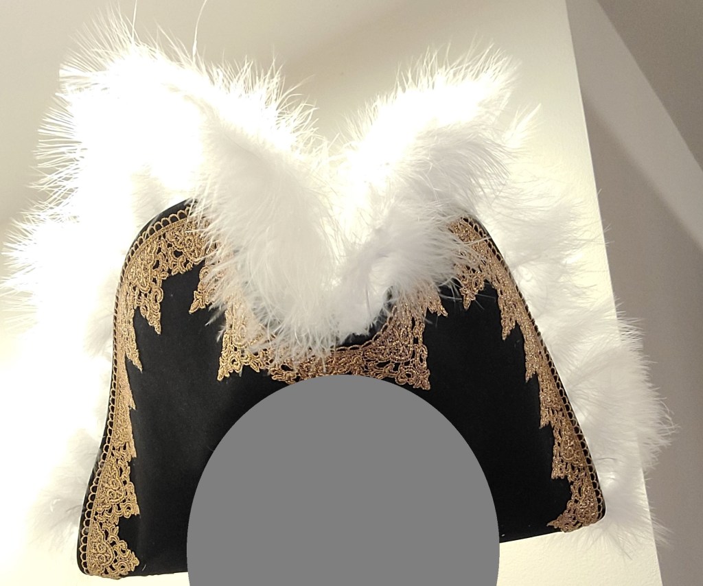
And the wall of hats is slightly more complete. Still needs something space themed. I’m thinking there might be a space helmet project in my future.

Ghostbusters/Luigi’s Mansion Mashup: Final Polterbuster

So, it’s been quite a while since I’ve posted, and at this rate I’m not sure I’ll be finishing a detailed description of the design and construction process anytime soon, so I’m gonna skip ahead a bit. If there’s enough interest in explaining the portions that I’ve skipped past (or I make myself take the time) I may circle back and explain.

Anyway, here we go. Through a lot of tinkering with 3D models, learning how to perform photogrammetry, and some hands on work, I finally finished the polterbuster, so now I have my completed costume.

I got the hand unit to hang off the side of the pack on the custom made mounting brackets with some magnets. Haven’t yet gotten the straps to handle the pack being unbalanced with the unit on it yet.

And now here’s everything put together. It was finished just in time for Halloween… when there was nowhere to go. Oh well, there’s always the next convention!

Maybe one day I’ll revisit this and get some decent sound effects added to it.

PolterBuster Project: Lighting

The clear compartment on the original vacuum contained a lot of white foam balls that got blown around by a fan when the toy was turned on. I decided that I was going to install lights here. The Poltergust from the games had one light… but this is an imprecise mashup piece. I decided to go with 4 lights, in homage to the proton packs, but green to match the aesthetic of Luigi’s Mansion.

Here’s what I was working with:

What I started with

I removed the foam balls, and originally I was also going to chuck the fan in the trash too, but I hold onto parts like that just in case, and I’m glad I did. This will be important for later.

Motor parts kept for later

For the lights I ordered some 10mm green LEDs (I like my tech chonky, especially for a cartoon character), and the accompanying resistors.

Chonky 10mm LED vs standard 5mm LED

I 3D modelled and printed a piece to hold them into place in the spacing I wanted, and after a lot of frustration and soldering I got them into the installed. I put a solderless connector on the end so that I can separate parts when troubleshooting and/or if I decided to mount the board on the other half of the casing. I really need to spend some more time practicing crimping those connections correctly.

Light array prototype for test fit
Hmm… a bit messy
Eh, good enough for a rough build
Installed in casing

To control the lights for a blinking pattern, I used a knockoff arduino nano and modified some simple code for it. Gotta watch out for those knockoff boards, though. I had to go find special drivers so I could use the board, which can be nervewracking. You never know what people are going to include in code from an obscure website.

Prototyping the simple code on my Uno
Nano board mid-construction… I forgot to take a closeup when I finished the soldering

To power the board, I decided to use a phone power bank, as I hoped it would be an easy solution… I should know better.

Early Tests

Hooking the board to the phone bank powered the lights…. for less than a minute. Then the power-saving features on the bank determined there wasn’t actually enough of a load on the circuit, and cut out. After a lot of fiddling with resistors, I added a bundle of 4 resistors in parallel to the circuit to add a little bit of load, which makes the power bank stay on.

And this is why we have breadboards and alligator clips.
Resistance is… helpful

Once I had verified that the power bank would stay on, I went to permanently install the components. I continued cannibalizing the cable I was using, and wired the resistor into the circuit. I also added the toy’s original power button into the circuit as it would be a conveniently accessible button already built into the casing.

There was a originally a casing on the resistor bundle, shown here, but I removed it later due to heating concerns

Of course, the one segment of the wire I HADN’T messed with turned out to have a short. I had to cannibalize another wire end to bypass it. (Not shown, just annoying)

Then I had to figure out how to mount everything so that it would stay in place and function reliably. I went by my old standby for mounting things: hook-and-loop-backed command strips.

Circuitry mounted on the back of the red shell
Power bank mounting location

I used the modified USB cable to connect the two halves together for closing up. I also added an extension cable for charging the power bank without opening up the case, and a cut a hole for checking the display of the power bank to determine the charge status.

Charge port at the top, status display in the middle

With that all wrapped up and functioning, here’s the light sequence. Pay no attention to the other changes for now.

PolterBuster Project: Backpack Mounting

I need to be able to wear this as a backpack. Conveniently, I found that the bottom had 3 wheels.

I carefully removed the wheels (just required removing the screws), and used the screw holes to mount some connecting rings.

Then I added some padded, adjustable straps. They weren’t quite the right length. The backpack dangled far too low on my back originally.

I ended up having to shorten the straps, cutting the stitches on one end, and restitching them at a better length. The ends dangle, and I’ll probably need to shorten and/or stitch them flat later for neatness, but at least they work now.

It’s not the best stitchwork, but it works well enough. Now the straps are in a range where, if anything, I might need to adjust the straps longer using the built in adjustment hardware. Just about where I wanted it. Shortening these straps didn’t take long at all to do.

PolterBuster Project: External Decorations

I’m starting some overdue updates on the backpack. I’ve decided to call it the PolterBuster for now. Just so I have a tag for these posts, and the build is a mashup of a Poltergust and Ghostbusters equipment.

In the previous post I mentioned where I got some of my inspiration from for the backpack, and showed what I started from.

This should probably usually be last, but I was solving problems as I went. There was a lot of text on the vacuum unrelated to it’s new life as a Poltergust. For the sides, that was an easy enough fix (as long as people aren’t looking TOO closely). I just sanded off the text, colored in the area with a black sharpie, and IMMEDIATELY rubbed off the excess ink with a dry paper towel. Seems to work okay. The same trick KINDA worked for a small section of the text on the red shell and a red sharpie, but I only used it for a small section where I was unable to fully cover up the text.

It’s an interesting trick I learned from a friend of mine. Too bad I realized later that it’s going to get covered up by some other parts as soon as I can make them, but now I have another trick up my sleeve.

For most of the rest of the text and symbols that I didn’t want, I covered them with what I thought were appropriate stickers.

Fun Fact: Boos are called Teresa in the Japanese version of the Mario franchise, hence why the Japanese text translates to “Teresa-busters”

The NES controller sticker covered the hole that a fake knob protrudes from, so I placed the sticker and used a hobby knife to trim the hole out.

I also decided I wanted to cover the fake power cable retraction button.

PEW PEW PEW.

Not much to cover in this particular post, but I’m trying to break these up by topic into manageable chunks.

Luigi’s Mansion/Ghostbusters Mashup Costume: Early Work-In-Progress

I’ve been playing a lot of Luigi’s Mansion lately (1 and 2, I don’t have a Switch for 3), and decided to combine costume ideas. Luigi in a modified Ghostbusters uniform.

Base uniform:

I started with the base jumpsuit with the Ghostbuster patches removed.

Then added Luigi’s hat and gloves. Mine is compatible with touchscreens!

Now for some replacement patches. I got the custom name patch from GBFans.com.

And the No Boo version of the No Ghost patch from a vendor on eBay.

I ain’t afraid of no Boo!

Belt & Accessories:

I liked the vintage style flashlight that Luigi carries at the start of the games before he picks up the backpack. I did some hunting on eBay, and acquired this one:

The bulb was dim and flickering, so I decided to replace it with an LED of equivalent size. While I had it open I removed a bit of corrosion from the battery spring and taped the split glass lens together to make it sturdier. I also found a holster to hold the flashlight on my belt.

I also needed Luigi’s version of a PKE meter, the Gameboy Horror. After a bit of eBay auctioning and retrofitting, I’ve got my own! I may cover more of what went into that in another post, but here’s the final result.

There is also a clear plastic clip that was sold as an aftermarket item to match.

I’m using the standard web-belt from the Ghostbusters uniform, so nothing fancy there.

The Backpack:

This portion will definitely require a post or more of it’s own. I’ve acquired most of the parts, but I’ve barely started on construction on it. I’m starting from this toy vacuum cleaner as the base:

I can’t claim credit for this part of the idea. I thought someone had likely tried to build this pack already, and of course someone had. I did a quick search on youtube and came across this video.

Obviously not my video. I’m glad I came across it, though.

I’m not planning on building the pack the same way he did, but it works as a good enough base. Mine is going to be my own interpretation of a mashup between the Ghostbusters proton pack and Luigi’s Poltergust.

Where I am so far:

So, just about everything except the pack is ready. Also, I’m not gonna be grooming the mustache or wearing a fake one, so I’m waiting on a cloth mask with a print of the lower half of Luigi’s face on it!

Here’s what I’ve got together so far:

I think it’s coming together nicely!

Space Mouse and New Soldering Iron

I’ve been doing some training to improve my 3D modelling skills with Autodesk Fusion 360 (not sponsored, that’s just what I use) lately, and in one of the videos the instructor mentioned that he happened to like using a 3D mouse to rotate the models and help his workflow be just that bit easier.

Around the same time, someone happened to drop this link in the cyberdeck discord chat.

https://www.instructables.com/Space-Mouse-With-Arduino-Micro-Fully-Printable/

It’s the instructions for a homemade spaced mouse with 3d printed casing. It uses a small arduino board and some inputs (buttons and a clickable joystick) to make a space mouse.

Hmm… I can build a space mouse for a fraction of the cost of one I could buy? I get a new device for my workflow AND a project to practice a bit more with electronics and code?

Well, that’s a no-brainer. Project ahoy!

So, I started following these instructions, and built my space mouse.

Side note: every time I use the term space mouse I think of Mickey in a spacesuit. I don’t know if anyone else has that issue, but I just had to share.

I don’t think I’m gonna get too in depth covering it, as that feels redundant with the instructable above. I will point out a few things form my experience though.

This project made me very glad that the arduino boards came in a multi pack. I botched the first attempt HARD.

I put pins along the entire length of the soldering locations. Where are the wires supposed to solder to if you’ve put pins in all the holes? WHERE???

Turns out I wasn’t reading the instructions closely enough.

In addition, I was attempting to solder things while the board was embedded in the case. That didn’t work to well either. There was nowhere for the iron to really fit. While I was at it, it reminded me that I was using a very cheap soldering iron that I had only bought for something to do heatset inserts with, which wasn’t as precise or controllable as I needed.

So, with all that, I decided to make a few changes to my process and equipment.

1. I reprinted the case. I’d… kinda melted the board into the original case already and couldn’t get it out.

2. I carefully reread the instructions, found a diagram of the pinout for the board, and made myself a detailed diagram to work from before soldering ANYTHING.

I only needed a few of the pins that came with the board to make things to mount the board to the case, not the entire row.

3. I used thinner, more flexible wires. The originals were waaaaay too inflexible to fit where I needed them.

4. I did all my soldering away from the plastic, then carefully installed the parts in. No unintentionally melted plastic.

5. I improved my soldering equipment and process. I made liberal use of solder flux (I’d shied away from it in the past), added a fume extractor to avoid having to work with the door open, and got a much better soldering iron after conferring with other makers about their recommendations. It was my third iron after all, it was time to get something that would work well. Finally got myself a Hakko.

Also took a little bit of time to do some reading/viewing so I’d take better care of this iron and have better soldering results.

This was a series that helped me, by the way. Sometimes you gotta go back to basics… and realize your bad habits that you’ve gotta fix.

6. For connecting to the joystick, I used solderless connections to save my sanity, since it came with connector pins on the stick already.

I’m pretty sure I redid this, but I didn’t take more photos later. You get the idea, though.

Anyway, after all that on the hardware side, I finally got the thing built. All the wires soldered, the thing assembled and closed up.

I used black for the optional button extensions because I thought it’d be easier to use with contrast.

I ran into an issue with the thing slipping around on my glass desk, so I pulled out the rubber tape that I used for my arch lamp to make this nonskid as well.

Now it doesn’t move anywhere unless I deliberately pull it off the desk.

Once I got the thing assembled and plugged up to the computer, I loaded the code included with the instructable.

Buuuuut…

The code was written primarily for this thing to work with Autodesk Inventor not Autodesk Fusion 360. The shortcuts are different in those two pieces of software. It took a bit of reading (particularly looking up the shortcuts for Fusion, figuring out the Keyboard. h code, and the firmware itself), but I eventually got at least the ability to orbit (rotate the view around the models) and zoom to work.

… also kinda had to swap the X and Y axes in the firmware. I might have gotten those two pins swapped on install. It works now, though!

Once I’ve used it a bit more, and thought more on what commands I use frequently, I’ll have to take the time to reprogram the buttons to do something useful.

Anyway, I got a new toy, got some more experience on these kinds of electronics projects, and had a reason to finally upgrade my electronics setup to be something more useable. Win!

Note: Yes, I know that isn’t the common spelling for useable, but usable doesn’t look right to me, and IT’S A VALID SPELLING, DAMMIT.

[END OF LINE]

ΠTar Flying V Cyberdeck

So, you may have noticed that I appeared to drop off the web for about a month. Well, I was busy trying to build a full-size cyberdeck in a month for VirtCon 2021. I took Adam Savage’s advice from his book Every Tool’s a Hammer and took advantage of the competition to set a deadline for myself in order to build a concept that’s been floating around my head for a bit.

Now I get to share the result with you.

I decided to continue with the transforming feature from the last one, and the musical instrument theme from the first one, so here’s the ΠTar Flying V Cyberdeck.

A 3d-printed deck based around the general outline of a Flying V electric guitar, folding from guitar mode to cratetop cyberdeck mode. The neck is made of 2020 Aluminum Extrusion (aluminum extrusion was one of the requirements of the competition).

Here’s how it transforms:

I haven’t yet documented this one as thoroughly as my last build, but I can share with you some of what I do have this time. I may be posting more about this down the line as I sort through my photos.

Here’s the in-universe “sales flyer” as if this were being sold at a small shop as a custom item. It includes the general specifications and basic operating instructions.

I’ve posted the STLs on thingiverse, here:

ΠTar Flying V

Virtcon 2021 Design Competition

I’ve been clearing my tasks and workspace in prep for this competition, hosted by the cyberdeck.cafe group. The rules were announced last week here:

https://cyberdeck.cafe/mix/virtcon-2021-comp

The competition has two categories:

Competition A: Design a thematic t-shirt for the cyberdeck.cafe group to use for merch (additional requirements on the above link).

Prize: VOXELAB Proxima Monochrome Resin Printer

Wow. A resin printer for a prize? Pretty awesome. But that’s not where my talents or interests lie. I’m more interested in:

Competition B: Designing a portable cyberdeck (additional requirements on the above link).

Prize: An EZFlex build plate or your design printed on a large 3d printer.

I have about a month to design and present a new cyberdeck, this time using aluminum extrusion or piping. Conveniently, I’ve had the basics of a design that fits these requirements in the back of my head for a while, but insufficient motivation to build it until now. The prize is nice, but I’m really in it for the impetus and deadline to build another design.

I tend to get a bit… quiet about the details of my competition builds, so you’ll probably have to wait to see the design until I’ve submitted my entry to the competition. I can tell you that I’m definitely gonna be using some components and concepts familiar to anyone who has seen my previous builds.

Most of the parts are at the sanctum or will be arriving soon. Most of my concept seems like it should be straightforward (which I think means I’m not grasping something) except for one thing the whole design hinges on, which might get iffy.

Points where I have been or will be doing some learning:

Components new to me for this build so far:

Aluminum 2020 extrusion

Fan-based cooling on a Pi

PiSugar 2 Pro for a Raspberry Pi 4B

MDF board

Processes I have a bit of concern over:

Printing large objects without warping:

I’ve been running tests this past week trying to adjust for some warping issues that I’ve had with large objects. I’ve built a temporary enclosure to reduce issues with drafts causing unequal cooling (I’d post it… but I think the current version is a rickety potential fire hazard that I don’t want to condone for others). I’ve also changed some of my print settings to help with adhesion. These include checking the bed levelling (I still may need to redo this), increasing the first layer temperature, adding a large brim… and simply avoiding the area of the printer that seems to run into the worst problems. Side benefit: I’ve rebuilt the arch lamp, and didn’t have to use tape or glue.

Cutting MDF:

I’m currently planning to use MDF for part of the design to cut down on the parts count. I can eliminate about 12 3d printed parts from the design if I use some kind of sheet material, and MDF seemed appropriate. There are two methods I have access to at the moment that I plan to try: 1) cutting with a reciprocating saw or 2) attempting the “score and snap” method. I’m expecting some difficulties with this, but even if it takes me a few attempts and a bit to figure out, it should still be better than printing all those additional parts. It should be a simpler and stronger build this way.

A Very Belated Project Post: Pi-Tar Final Steps and Anatomy

As you’ve probably been able to tell from the dedicated page on the website, I finished the Pi-Tar months ago, but I never got around to explaining the final construction of it. 2020 was a hell of a year.

Looks like I left off after adding a power switch to the casing. I apologize in advance for lack of detail on certain aspects, I’m catching up on something from months and a few projects ago.

USB Hub:

In order to offload some power requirements for additional USB peripherals from drawing power through the Pi, as well as to make a more convenient location for plugging things in, I decided to add a powered USB hub. As an added bonus, this one came with an SD card slot and a microSD card slot.

This did add some complicating factors, though. I needed the wires to fit through some pre-existing holes in the casing AND the thing uses USB-C. I ended up having to buy some additional parts to make this work, which got rather weird. I had to find a USB-A to USB-C cable that would connect to the Pi on one end and fit into the existing hole into the casing. I made that part work, but it took some finagling with the wires.

I also had to find a USB-C to USB-C connector to connect that wire inside the case to the USB hub.

I also had to add a micro-USB power switch cable to connect the hub to the power bank (as mentioned in a previous post), and I attempted to modify the cable coming from the Pi to avoid drawing from or backfeeding to the Raspberry Pi (I can’t remember if I ever got that part to work without losing power, but that was the intent).

Once I figured out the wiring, I then had to figure out how to attach the thing to the exterior of the casing. Originally I was going to use the USB hub as the basis of some sort of pseudo-cartridge system with USB drives, but eventually cut it down to just being a conveniently accessible hub.

As part of this, I also decided that I needed to move the large audio port to the exterior of the case, and add an additional regular-sized audio jack. Moving the port freed up the existing hole in the casing to pass through all the wires for the interface hub. This meant I didn’t have to try to cut or drill a new whole in the interface between the two halves of the shell.

This hole, which is in the top right of the original casing

The 3D modelling and physically attaching that in was troublesome, but electronically it was simple. I just added an audio splitter cable to the end, putting one female end exterior to the case and the other connected to the adapter I had already been using.

I went through a LOT of iterations with the interface module (one of the names I’ve been workshopping, may be subject to change), and eventually settled on a two-part assembly that screwed onto the casing through existing holes. It took a LOT of measuring and iterations to get it to fit reasonably, both with the electronic components and the actual casing. I designed it in two parts, with the larger portion (containing the hub itself) screwing directly onto the casing, and the smaller portion (containing the audio jacks) sliding onto the larger part, and then screwing into both the casing and the larger interface section. The smaller section also served the purpose of covering the hole that the wires went through.

I quickly learned in that process to only print as much of a model as I actually needed to test the fit of parts, in order to reduce turnaround time and materials wastage. I also found out that parts moving in different directions can lead to weird shenanigans, like installing one part causing another to become unplugged.

Once I got that figured out and painted up (along with the new power switch), I finally assembled it for the last time. That was… interesting.

Final Assembly:

There are a lot of parts of this assembly that have to be done in a specific (and weird) order or else it physically cannot be assembled. Connecting the Raspberry Pi, it’s case, and the interface between those wires and the shell is a very delicate process of going back and forth and making sure that you don’t crush ribbon cables while also carefully routing wires before and after attaching the cable interface (the bit with the universal greeblie).

Connecting the top and bottom halves is also fraught with issues (having to carefully move wires to lay properly while closing the shells), and you have to do that before you can even start on attaching the interface module. I know I’ve missed many steps in documenting this process, including some that anyone crazy enough to attempt recreating this might want, but I’ve only got so much time and patience at the moment. What madman decided to design from a pre-existing case this way?

Oh, wait, that was me. Ahem.

If you have further questions, please let me know what you would like to know more about and I can see about adding it.

Grand Tour:

Note: the stuff on the end of the grip handle and anything in pewter color is purely decorative and non-functional.

Top View
Keyboard slides out of tray for charging
Internals
Interface Module End View
For further reference.
Back View
Recommended dose of geek-punkification

This has been a long project and a valuable learning experience. I learned more about Raspberry Pi (both from a hardware and software perspective), spraypainting, 3D modelling, 3D printing, electronics work (soldering), managing the details of a project, and working with professionals when I needed parts that I couldn’t yet make myself. I’ve even made new hobby contacts in the process who have helped me pick up more skills and helped out on other projects such as the Warp Core Lamp and encouraged me to make the Pioneer Falchion as another project.

I call this project “complete,” but as with a lot of other makers, this is more of a “project made it to baseline.” I’ve got some improvements I’d like to make (better power supply, attaching a headmounted display, making the Pi swappable as new models are released), but I’ve at least reached the initial goals I made before too much scope creep got in the way.

You may see more of the Pi-Tar (and possibly a sequel?) if/when I make upgrades to it.