
As you’ve probably been able to tell from the dedicated page on the website, I finished the Pi-Tar months ago, but I never got around to explaining the final construction of it. 2020 was a hell of a year.
Looks like I left off after adding a power switch to the casing. I apologize in advance for lack of detail on certain aspects, I’m catching up on something from months and a few projects ago.
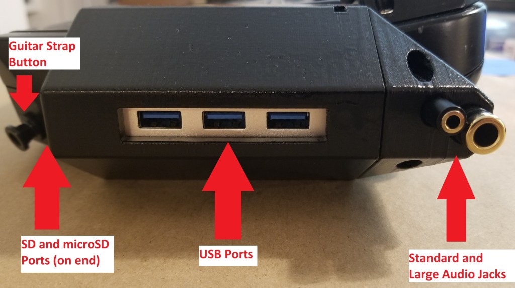
USB Hub:
In order to offload some power requirements for additional USB peripherals from drawing power through the Pi, as well as to make a more convenient location for plugging things in, I decided to add a powered USB hub. As an added bonus, this one came with an SD card slot and a microSD card slot.

This did add some complicating factors, though. I needed the wires to fit through some pre-existing holes in the casing AND the thing uses USB-C. I ended up having to buy some additional parts to make this work, which got rather weird. I had to find a USB-A to USB-C cable that would connect to the Pi on one end and fit into the existing hole into the casing. I made that part work, but it took some finagling with the wires.
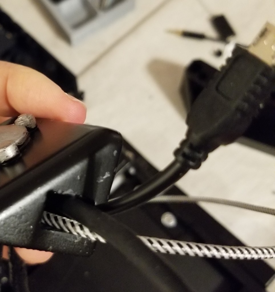
I also had to find a USB-C to USB-C connector to connect that wire inside the case to the USB hub.

I also had to add a micro-USB power switch cable to connect the hub to the power bank (as mentioned in a previous post), and I attempted to modify the cable coming from the Pi to avoid drawing from or backfeeding to the Raspberry Pi (I can’t remember if I ever got that part to work without losing power, but that was the intent).
Once I figured out the wiring, I then had to figure out how to attach the thing to the exterior of the casing. Originally I was going to use the USB hub as the basis of some sort of pseudo-cartridge system with USB drives, but eventually cut it down to just being a conveniently accessible hub.
As part of this, I also decided that I needed to move the large audio port to the exterior of the case, and add an additional regular-sized audio jack. Moving the port freed up the existing hole in the casing to pass through all the wires for the interface hub. This meant I didn’t have to try to cut or drill a new whole in the interface between the two halves of the shell.

The 3D modelling and physically attaching that in was troublesome, but electronically it was simple. I just added an audio splitter cable to the end, putting one female end exterior to the case and the other connected to the adapter I had already been using.
I went through a LOT of iterations with the interface module (one of the names I’ve been workshopping, may be subject to change), and eventually settled on a two-part assembly that screwed onto the casing through existing holes. It took a LOT of measuring and iterations to get it to fit reasonably, both with the electronic components and the actual casing. I designed it in two parts, with the larger portion (containing the hub itself) screwing directly onto the casing, and the smaller portion (containing the audio jacks) sliding onto the larger part, and then screwing into both the casing and the larger interface section. The smaller section also served the purpose of covering the hole that the wires went through.


I quickly learned in that process to only print as much of a model as I actually needed to test the fit of parts, in order to reduce turnaround time and materials wastage. I also found out that parts moving in different directions can lead to weird shenanigans, like installing one part causing another to become unplugged.
Once I got that figured out and painted up (along with the new power switch), I finally assembled it for the last time. That was… interesting.
Final Assembly:

There are a lot of parts of this assembly that have to be done in a specific (and weird) order or else it physically cannot be assembled. Connecting the Raspberry Pi, it’s case, and the interface between those wires and the shell is a very delicate process of going back and forth and making sure that you don’t crush ribbon cables while also carefully routing wires before and after attaching the cable interface (the bit with the universal greeblie).
Connecting the top and bottom halves is also fraught with issues (having to carefully move wires to lay properly while closing the shells), and you have to do that before you can even start on attaching the interface module. I know I’ve missed many steps in documenting this process, including some that anyone crazy enough to attempt recreating this might want, but I’ve only got so much time and patience at the moment. What madman decided to design from a pre-existing case this way?
Oh, wait, that was me. Ahem.
If you have further questions, please let me know what you would like to know more about and I can see about adding it.
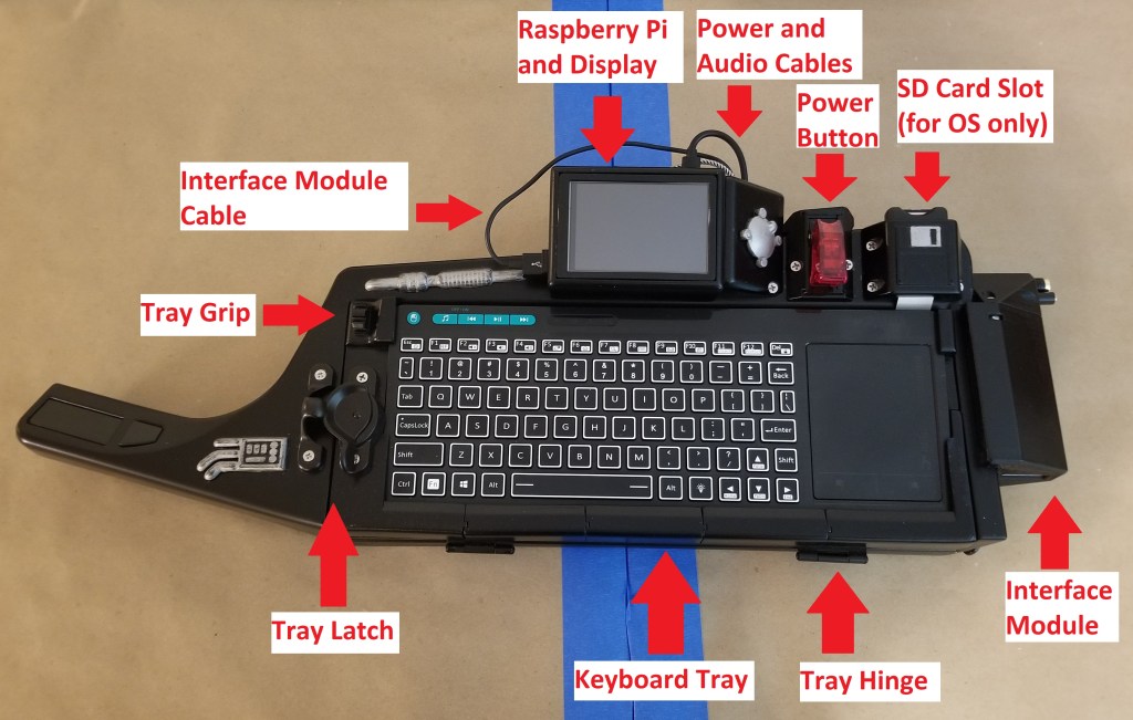
Grand Tour:
Note: the stuff on the end of the grip handle and anything in pewter color is purely decorative and non-functional.


This has been a long project and a valuable learning experience. I learned more about Raspberry Pi (both from a hardware and software perspective), spraypainting, 3D modelling, 3D printing, electronics work (soldering), managing the details of a project, and working with professionals when I needed parts that I couldn’t yet make myself. I’ve even made new hobby contacts in the process who have helped me pick up more skills and helped out on other projects such as the Warp Core Lamp and encouraged me to make the Pioneer Falchion as another project.
I call this project “complete,” but as with a lot of other makers, this is more of a “project made it to baseline.” I’ve got some improvements I’d like to make (better power supply, attaching a headmounted display, making the Pi swappable as new models are released), but I’ve at least reached the initial goals I made before too much scope creep got in the way.
You may see more of the Pi-Tar (and possibly a sequel?) if/when I make upgrades to it.
