
Early design phase:

Full Scale Sketch 
Early Components Layout 
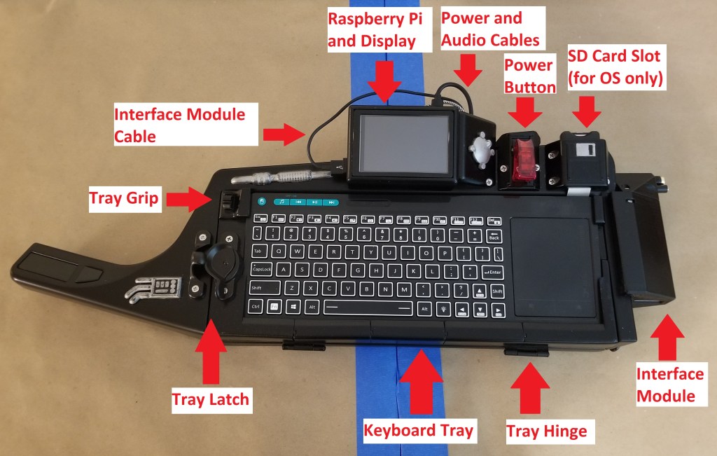
Remembering the Power Button 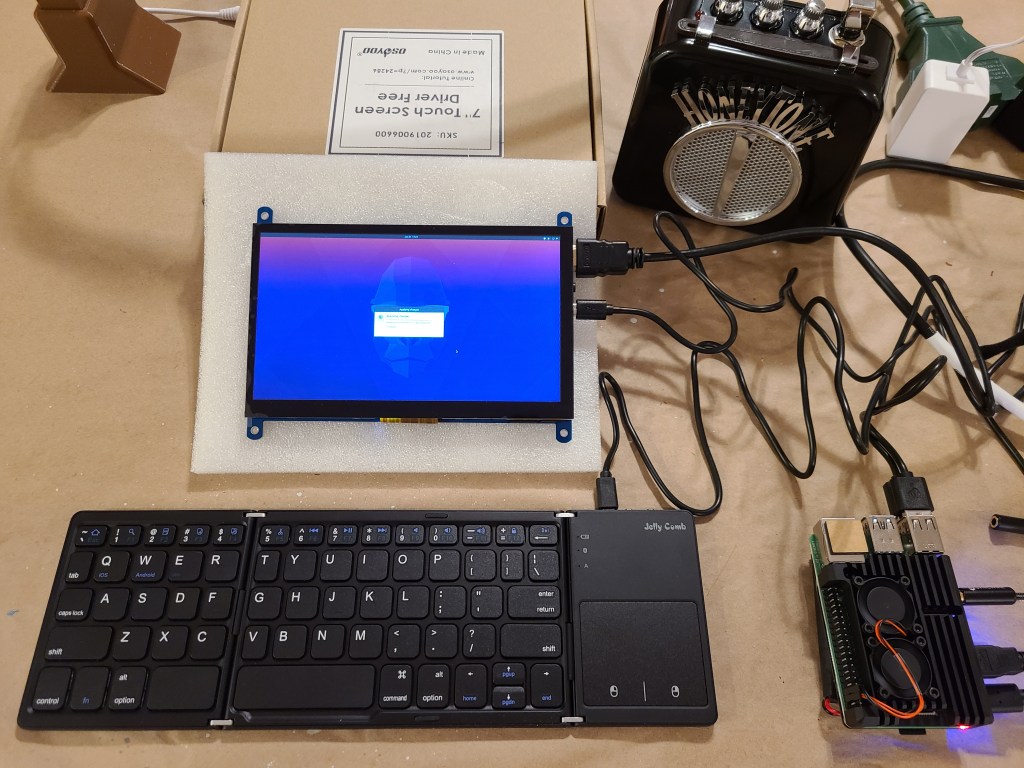
Testing the Electronics
Here’s some of the early stuff I went through, starting from making a sketch to figure out the angles to make the triangles in order to fit the components, and an early test to make sure the electronic components could work together.
Guitar Neck and Head:
The neck was easy to construct from components I had ordered. I 3D printed the head first as it could be designed and printed independently of the rest of the guitar while I took time designing the interdependent body sections. I originally intended to use a USB cable and an ethernet cable as fake “guitar strings”, but dealing with the cables would have added another layer of complexity that I didn’t need to deal with in the timeline of a competition project.

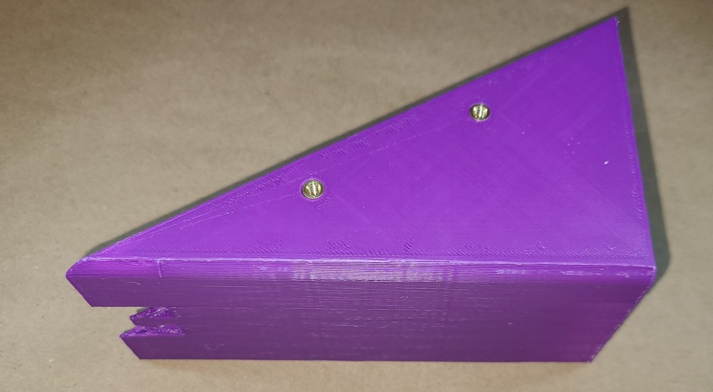
Open 
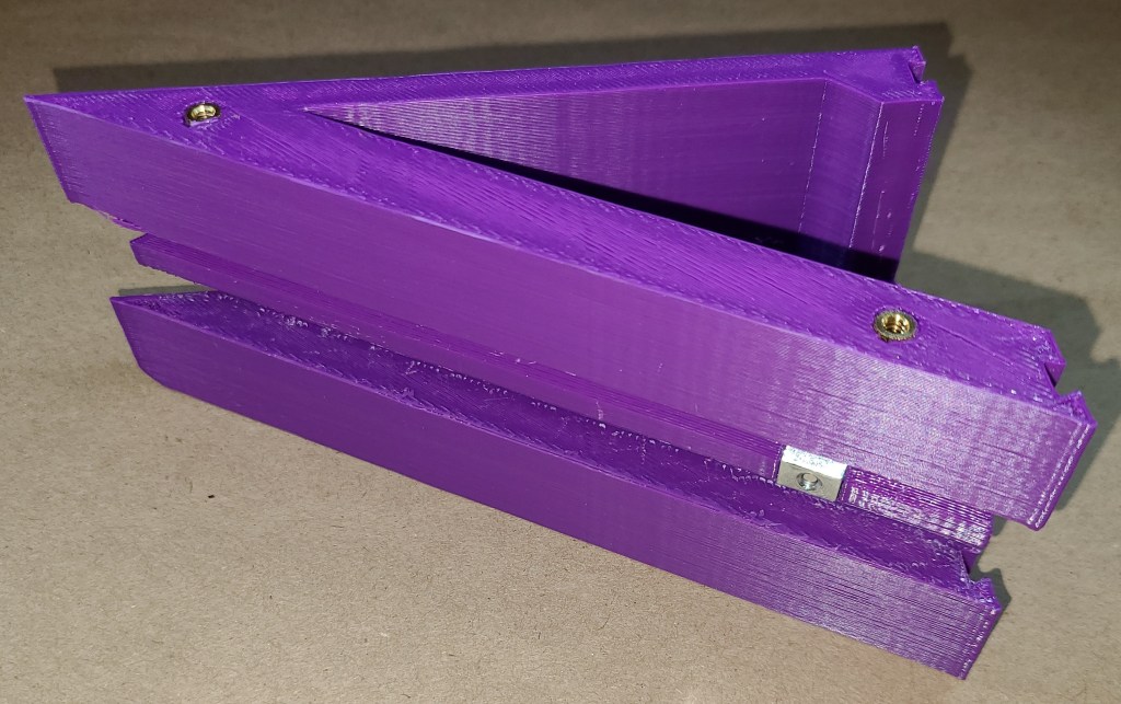
Closed. Detail on joint assembly. 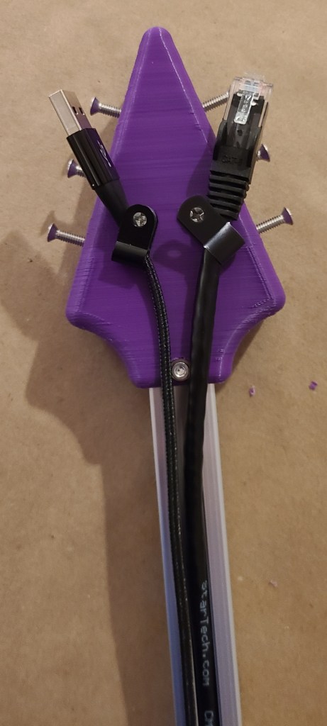
Test for cables as “guitar strings” 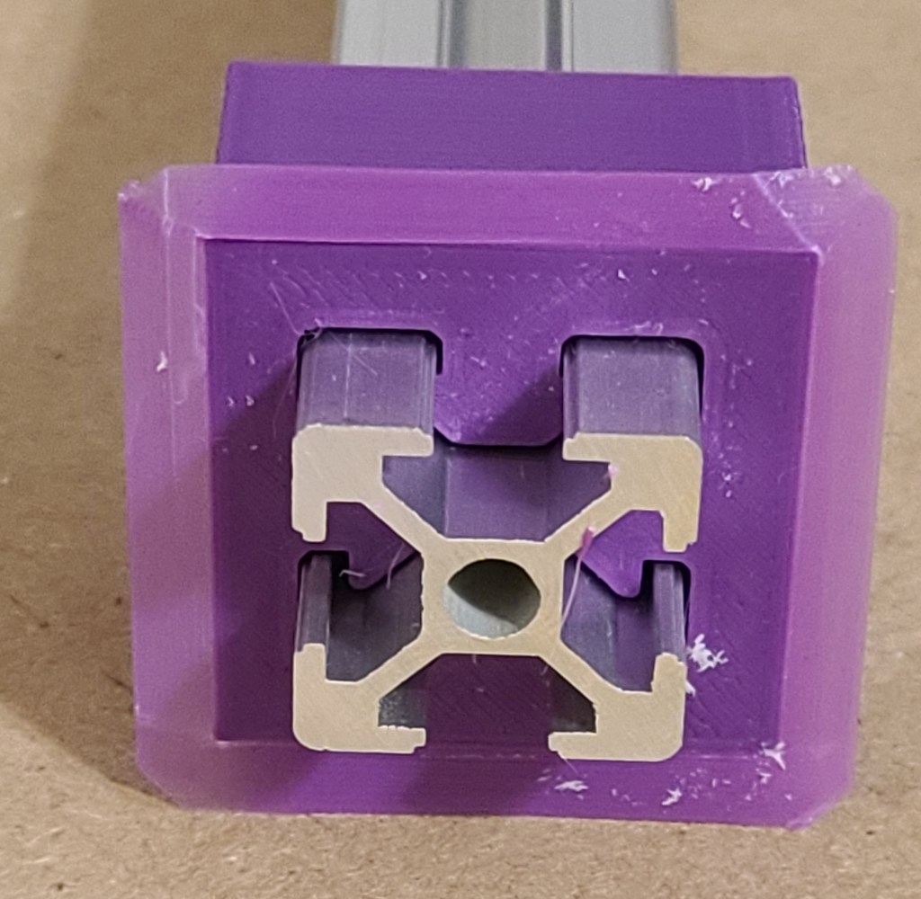
Testing 2020 connection 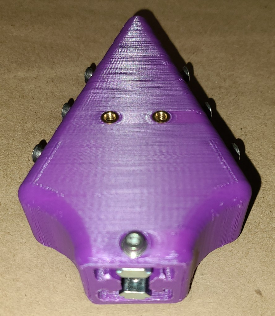
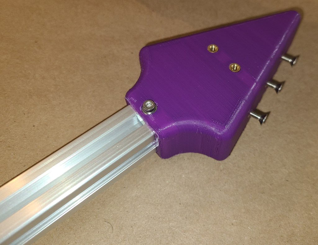
I modelled 2020 extrusion in CAD in order to use offsets to create interfacing components. This was included in various forms in the guitar head and the keyboard body. I also left spaces for t-slot nuts to attach to the neck. I put in screws in place of tuning pegs. Eventually I’m considering some changes such as thickening the head (to better support the monitor) and adding some decorative (or functional) fake tuning pegs, perhaps with SD cards in them.
Keyboard Sections:
I designed these sections next after the head, as the were the next comparatively simplest section, and I needed to get parts in production ASAP, using the print time of the simplest parts to design the next parts to print. This section connects directly to the guitar neck, and contains the ball joint hinge connecting to the monitor section. It also houses the keyboard and the second guitar strap button for wearing the guitar around.
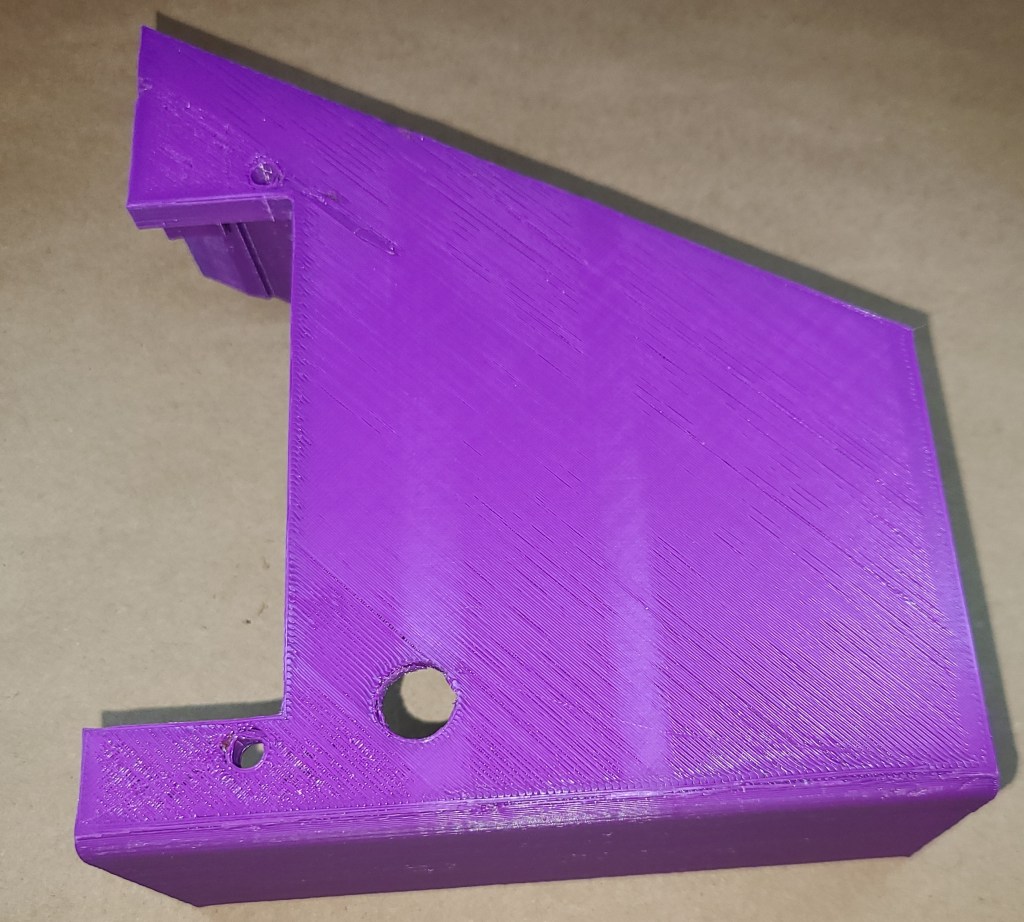
Keyboard 1:
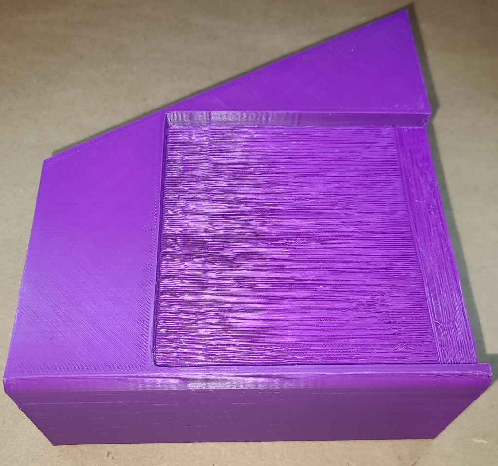
This section’s primary features are the connections for the latch, the plastic section designed to slide into the 2020 extrusion, and the added t-slot nut to allow to clamp solidly to the extrusion.

Keyboard 2:
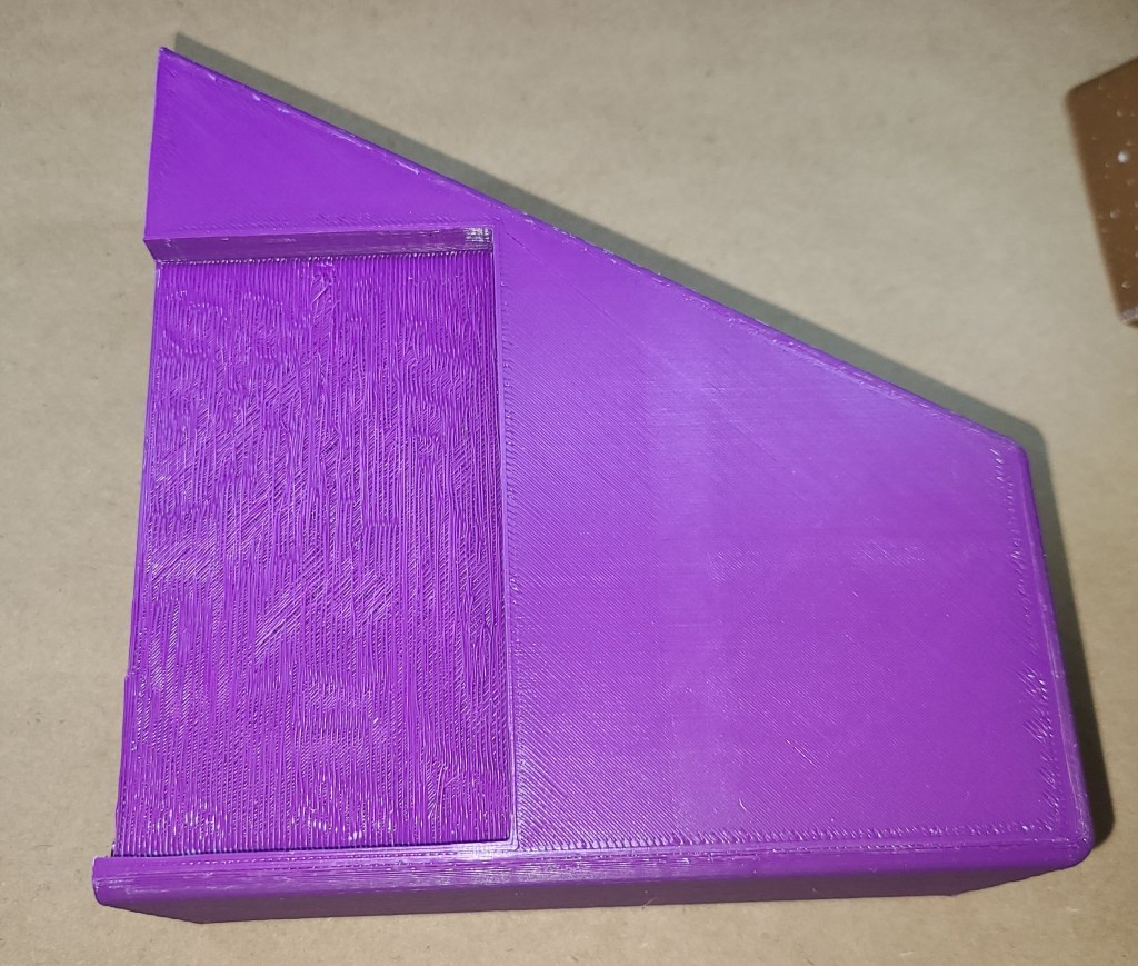
This section is the beginnings of the slot to hold the keyboard in place. It also continues the trend of t-slot nuts to hold onto the rail.


Keyboard 3:
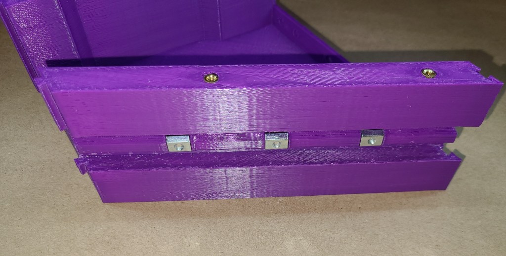
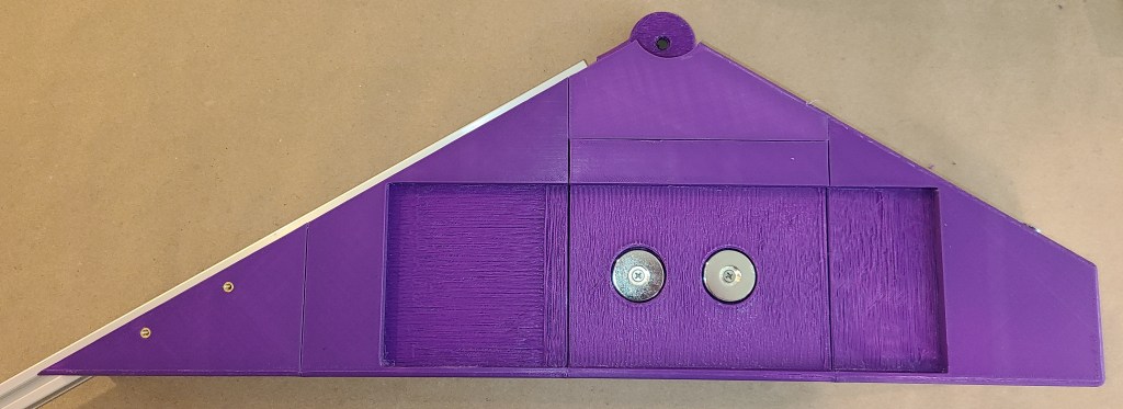
This section houses the magnets that hold the keyboard onto the guitar.


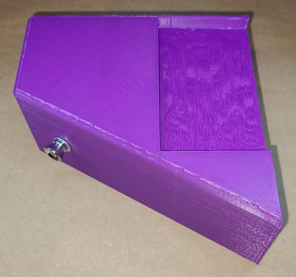
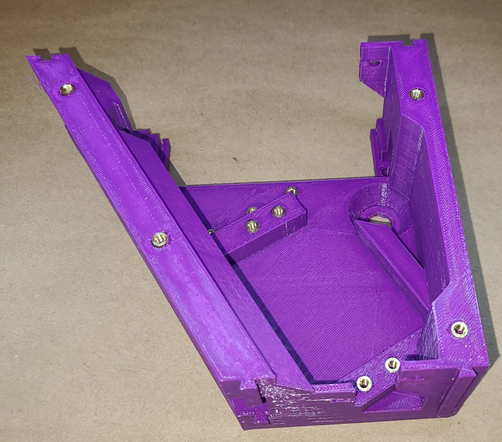
Keyboard 4:
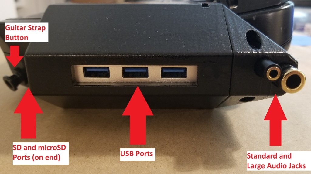
This part holds the remainder of the keyboard, as well as the guitar strap button for wearing the guitar around. At some point I want to slightly redesign this so that in the upper right of the keyboard slot there is space for access to the keyboard’s power button and a wire connecting the keyboard physically to the Pi instead of relying on bluetooth.

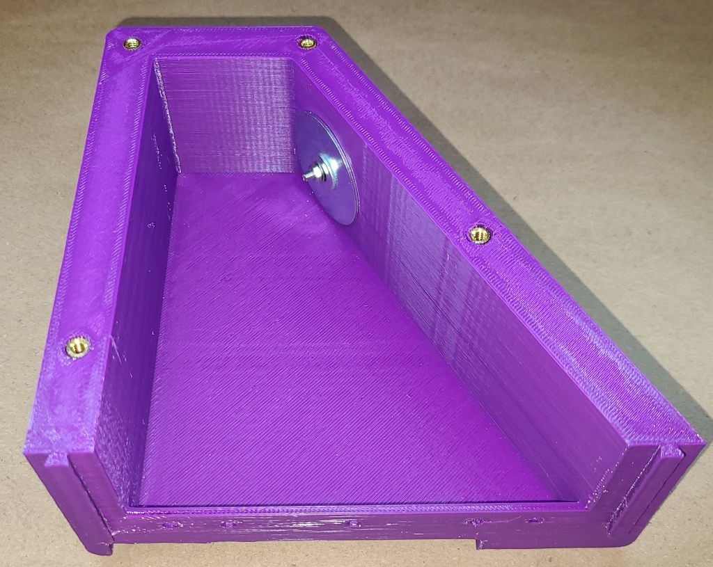
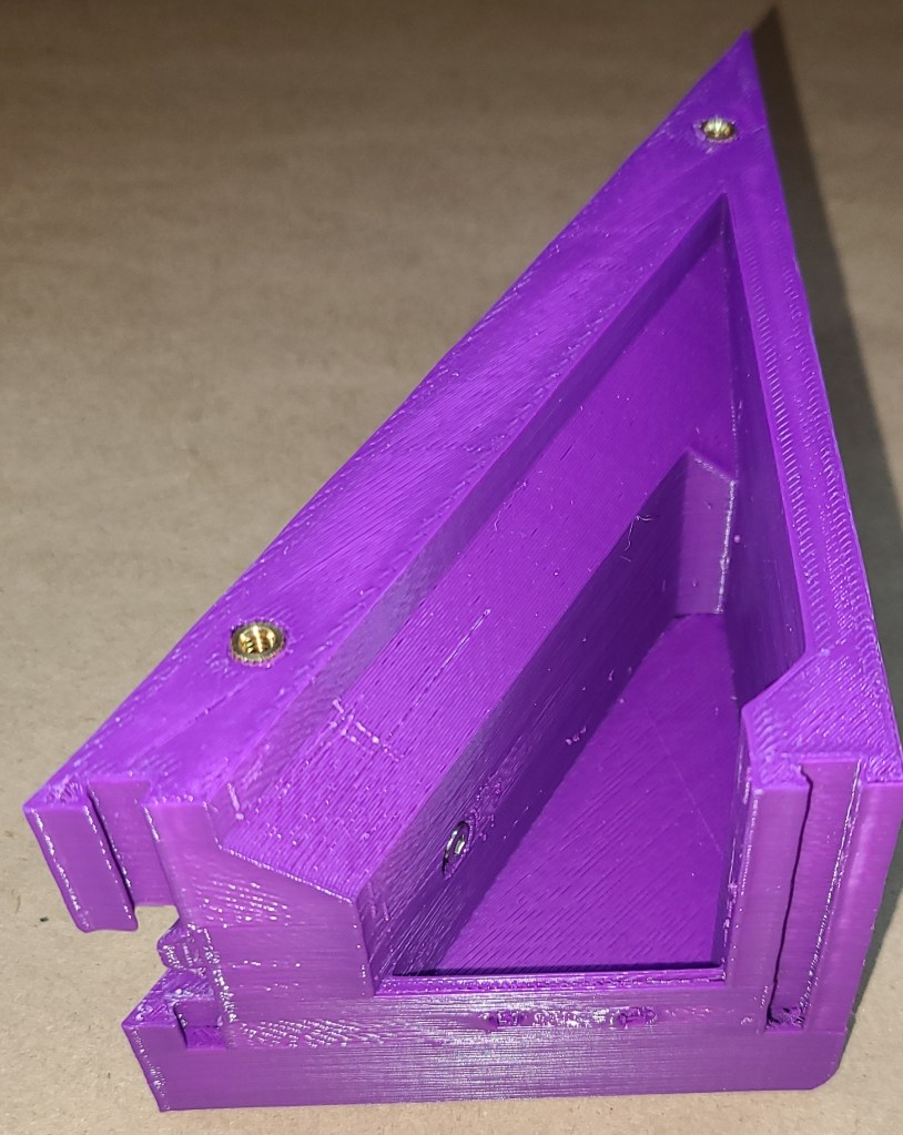
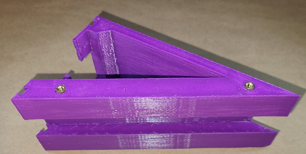
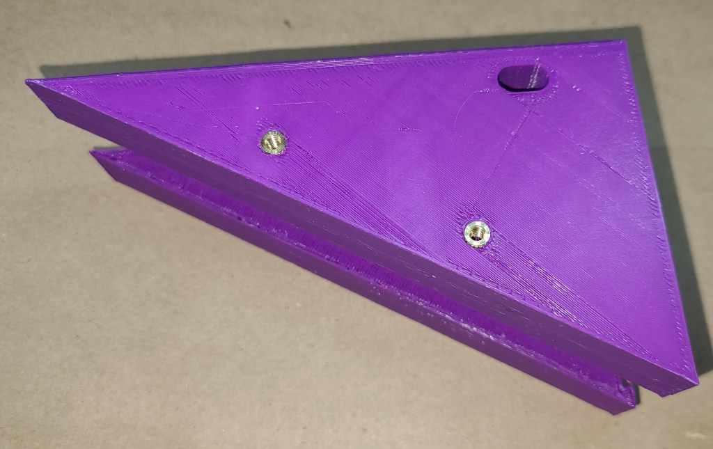
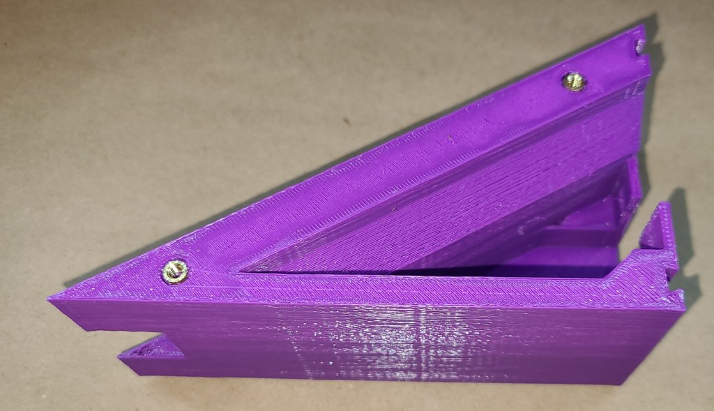
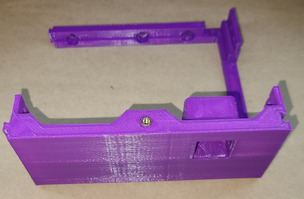
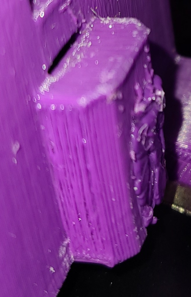
Keyboard Joint:
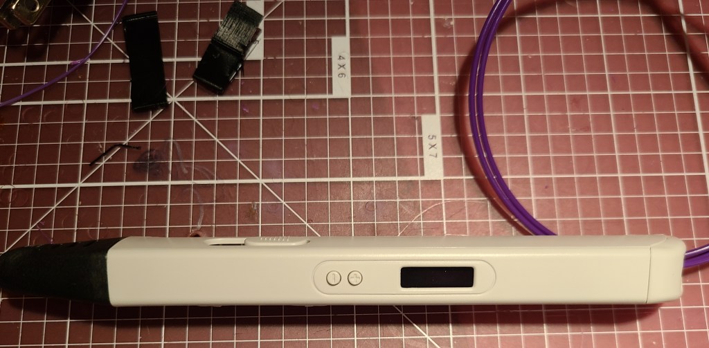
This had to be designed closely in tandem with the monitor side of this joint. This section’s purpose was to be solidly mechanically connected to the keyboard half, and hold the ball joint connecting the two halves together. There’s a space for a screw on the bottom to attach the ball joint, and a space and end-stop for a bold sticking out of the side of the ball joint. An accident after assembly caused the bolt to break straight through the end stop. Conveniently, I had recently added a 3D printing pen to my arsenal, and rebuilt the stop by hand in the same plastic… just much denser than it had been when it was originally printed.


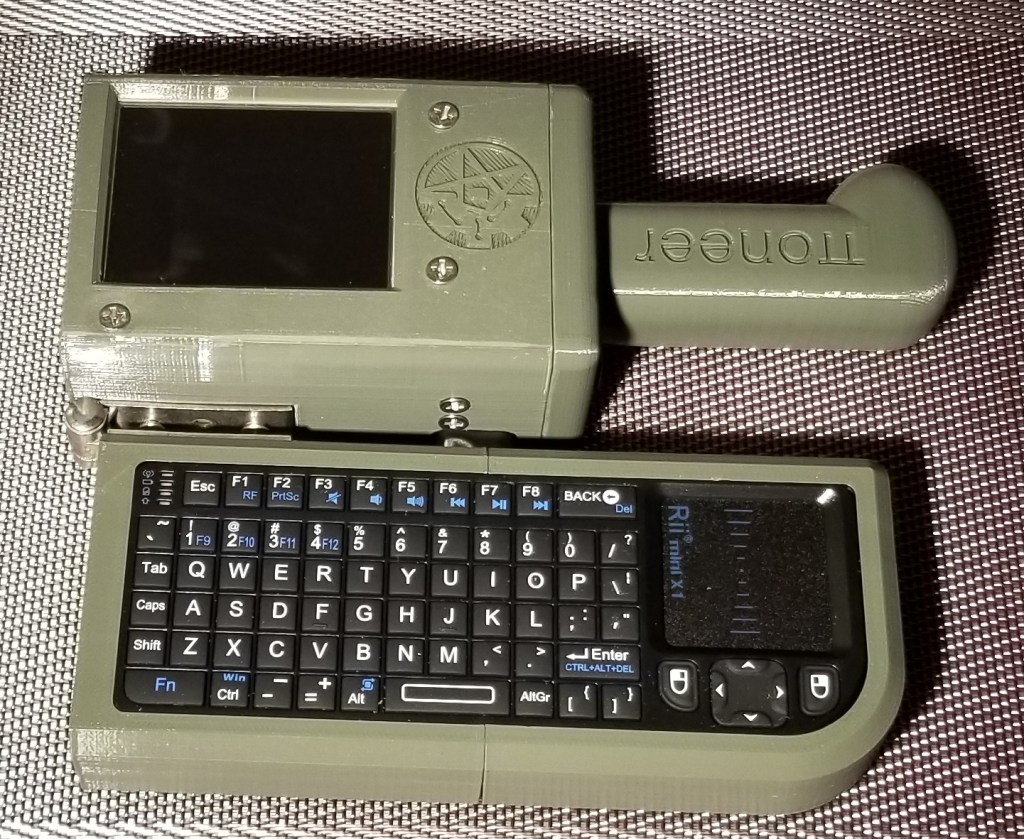
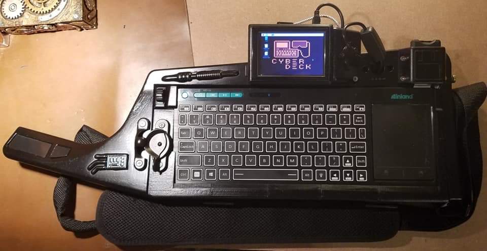
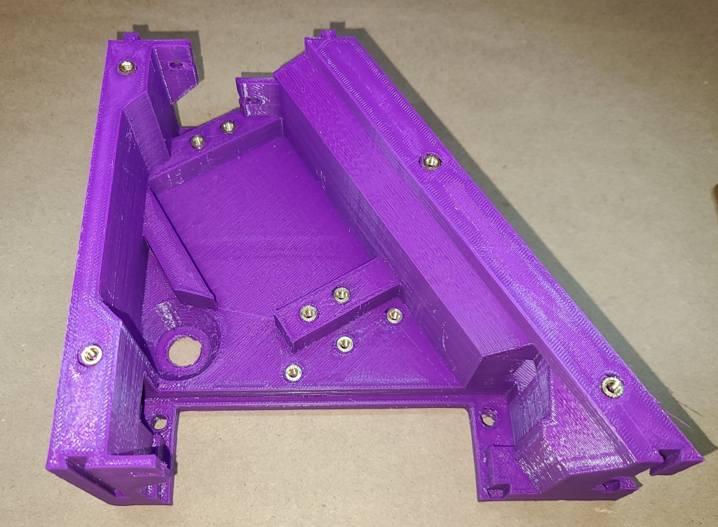
Keyboard Section Assembled:

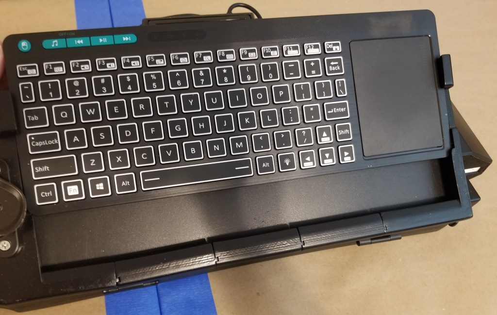
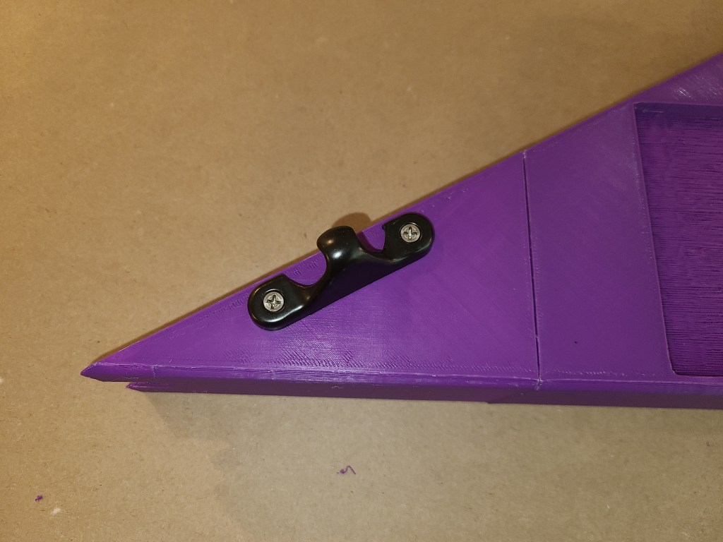
Keyboard Attachment:
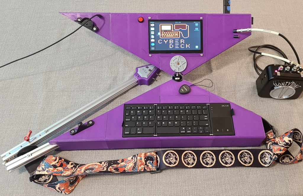
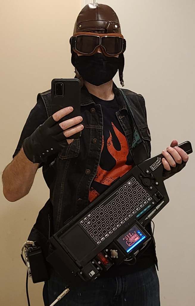
The magnets are used to attach the keyboard, which can be folded up to avoid being too obviously a computer. They keyboard then folds out to lay flush in the slot. I had to add tabs to get an easy grip on the keyboard to fold it back closed. Another item on my to-do list if I rebuild this is finger slots for grabbing the edges of the keyboard, for a cleaner build.

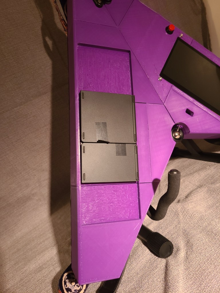

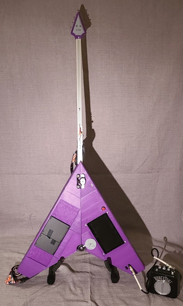
Note: They keyboard section could use a bit more weight to offset the weight of the monitor. The monitor tries to make the whole thing lean backwards a bit. For now, the guitar-neck kickstand partially compensates. Thickening the head of the guitar to match the thickness of the body would also help.
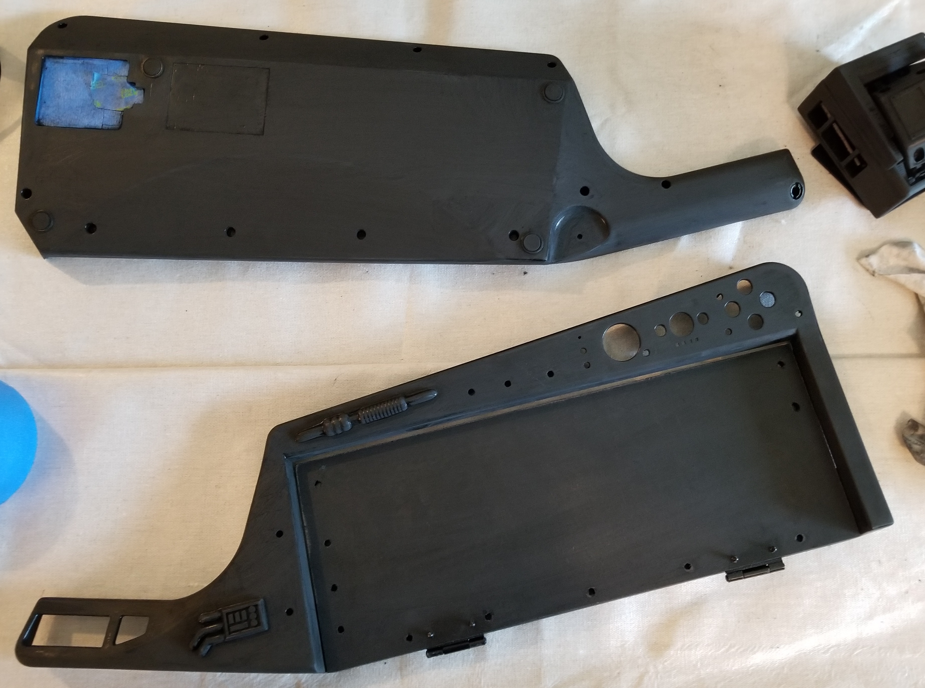
Monitor Sections:
This section was one of the last things I designed due to to complexity and the need to get stuff to the printer as fast as possible.
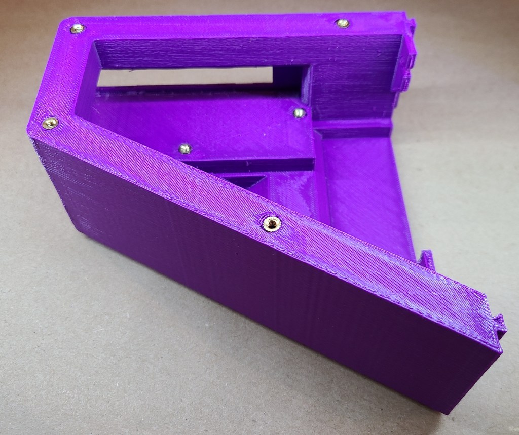
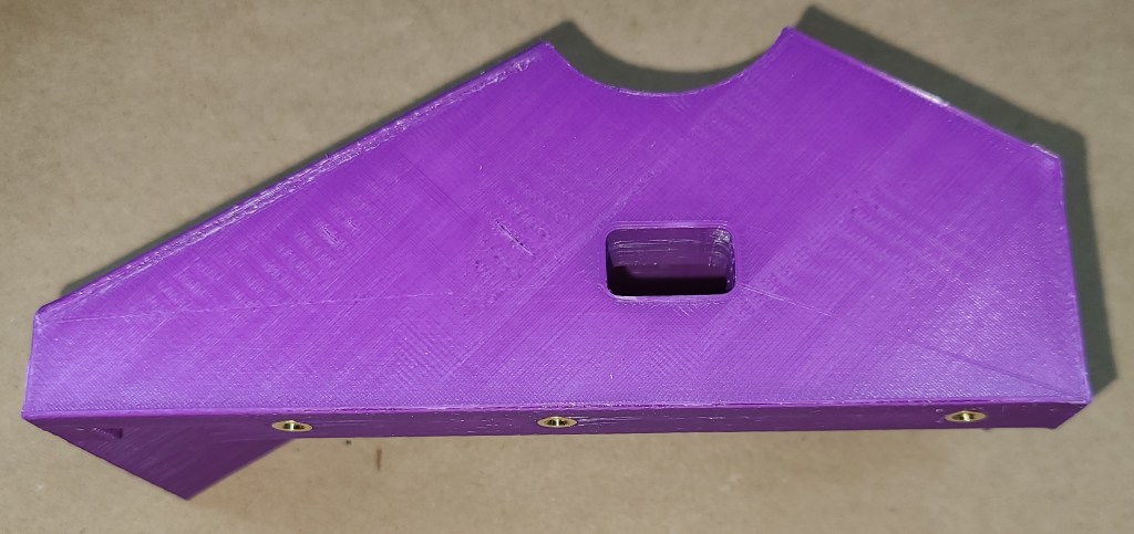
Monitor 1:
This section includes the hole for the charging port cable and mounting points for the latch that holds the guitar closed.
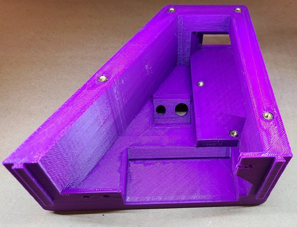
Monitor 2:
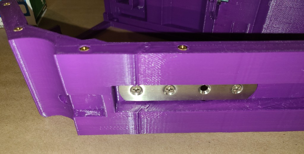
This section has the slot for the battery pack, one side of the mounting holes for the Raspberry Pi mount, a hole for the power switch, and part of the space and connections for the monitor. There is also an extended gap and mounting holes in the section near the 2020 extrusion, where I later installed a metal strap to rigidize the connection between this section and the hinge. Without that strap that connection would have been far too weak.

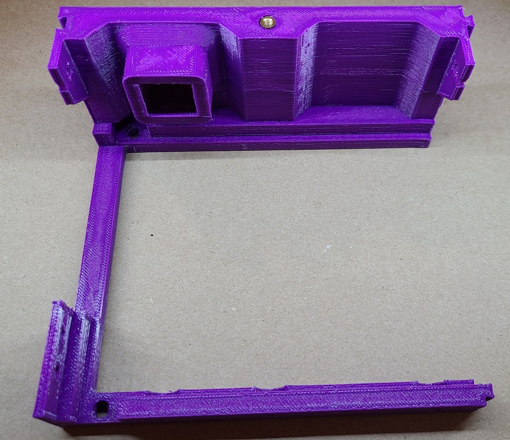
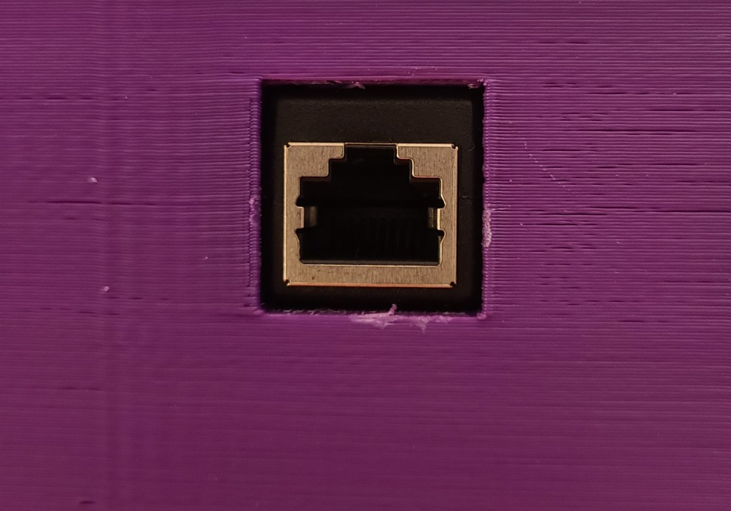
Monitor 3:
This section holds the majority of the monitor, and the ethernet port.


Monitor 4:
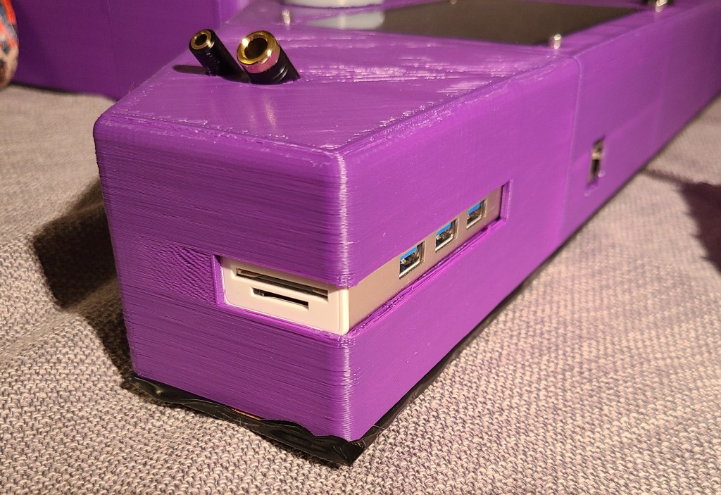
This section includes the holes for the audio jacks, the slot for the USB hub, and a recessed section to accommodate the cables coming out of the side of the monitor.


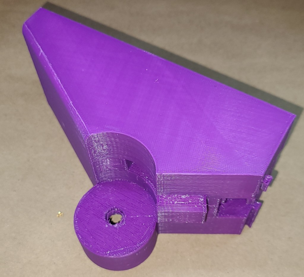
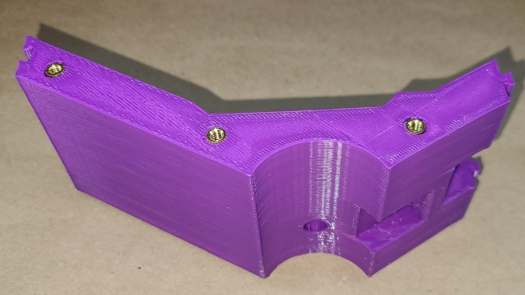
Monitor Hinge:
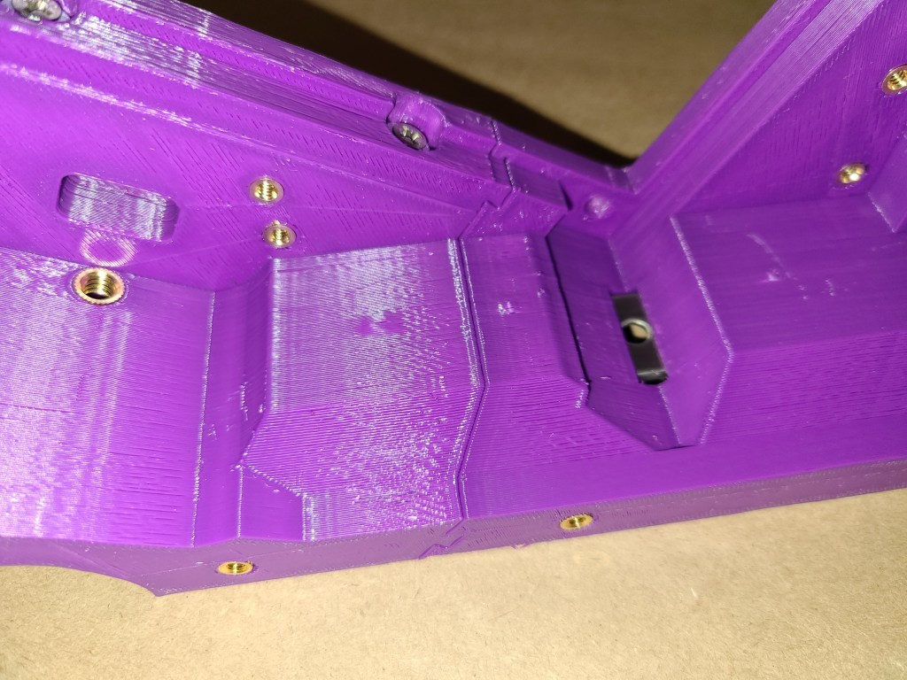
The hinge sections were crazy, trying to deal with the ball joint. This half also had to accommodate a metal strap connection to monitor 2, connection points for the Raspberry Pi mount, a hole for possible future expansion, and a slightly different sideways connection to monitor 3.


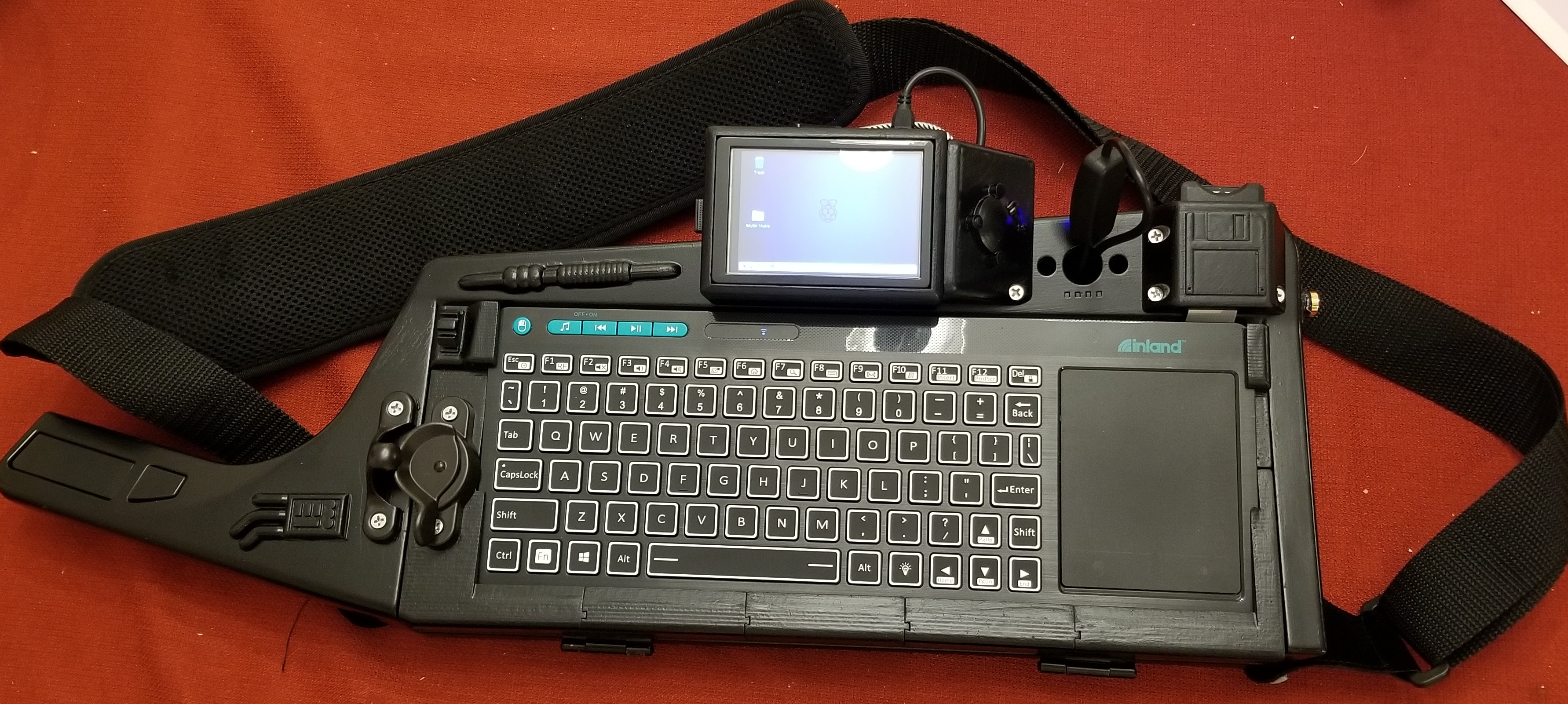
Monitor Assembled:
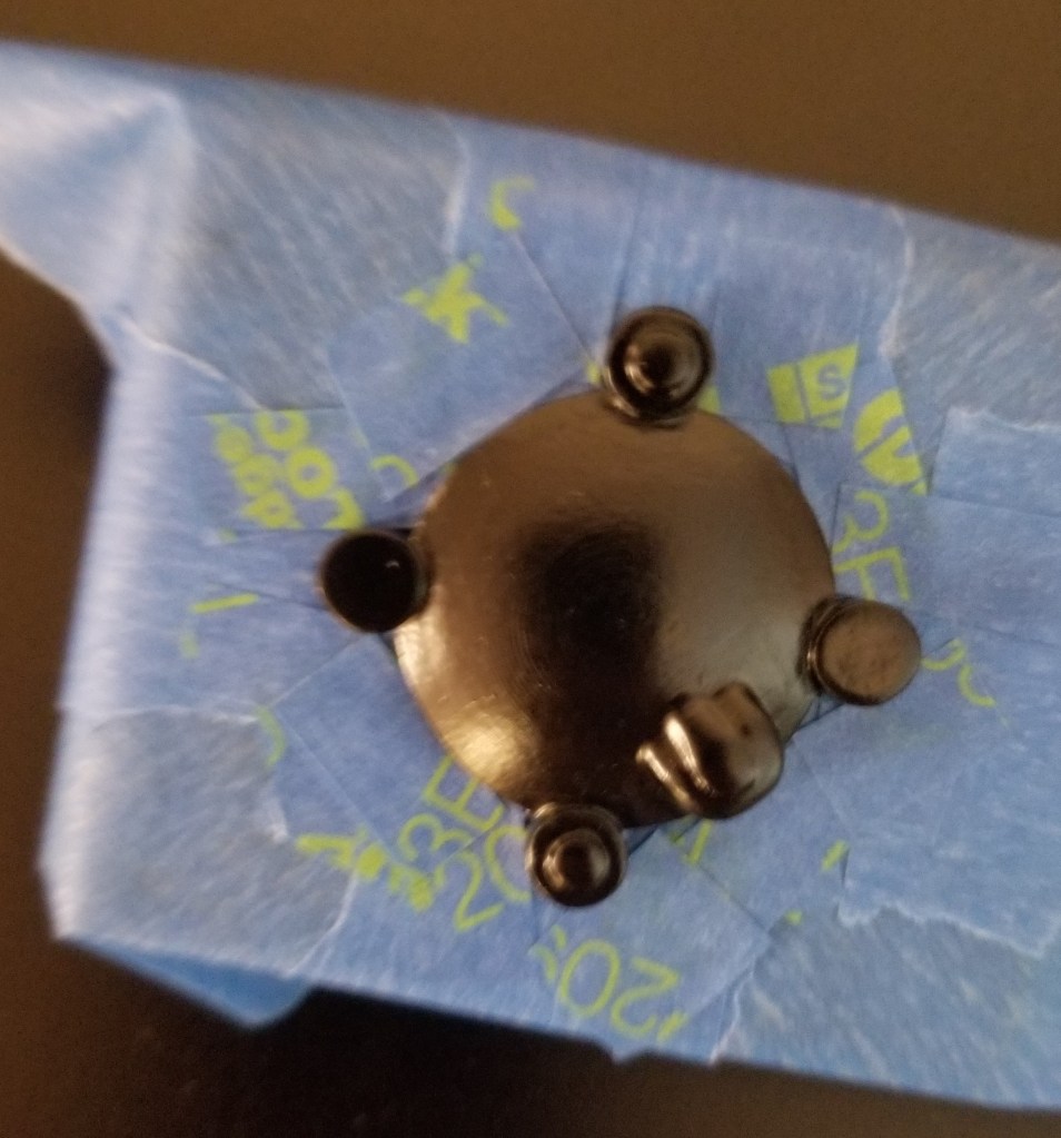
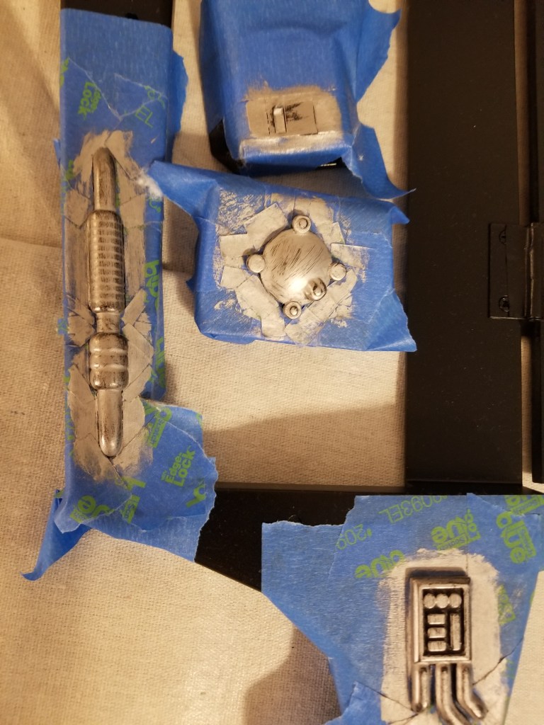
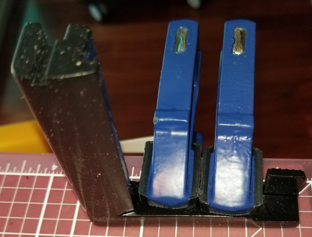
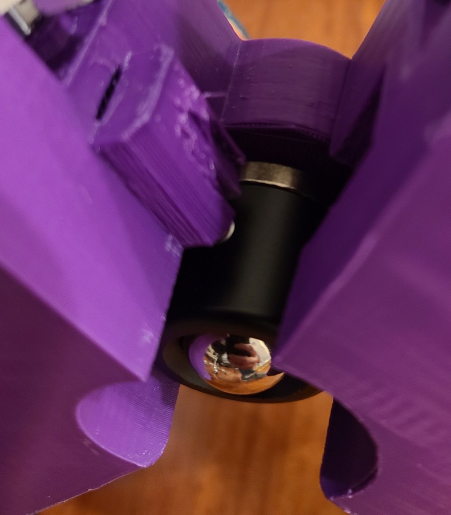
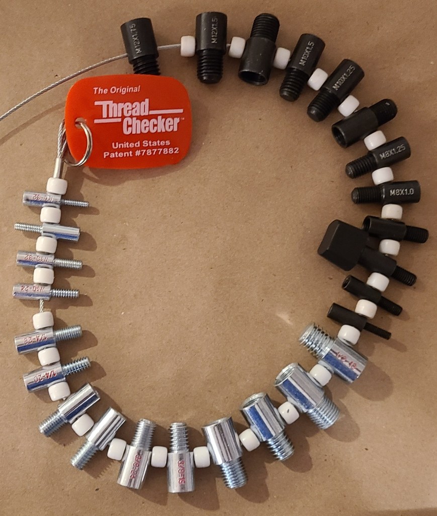
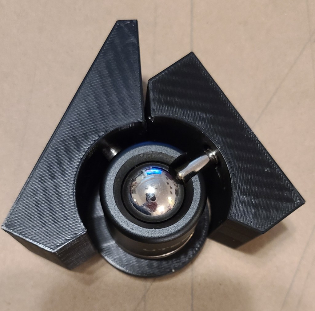
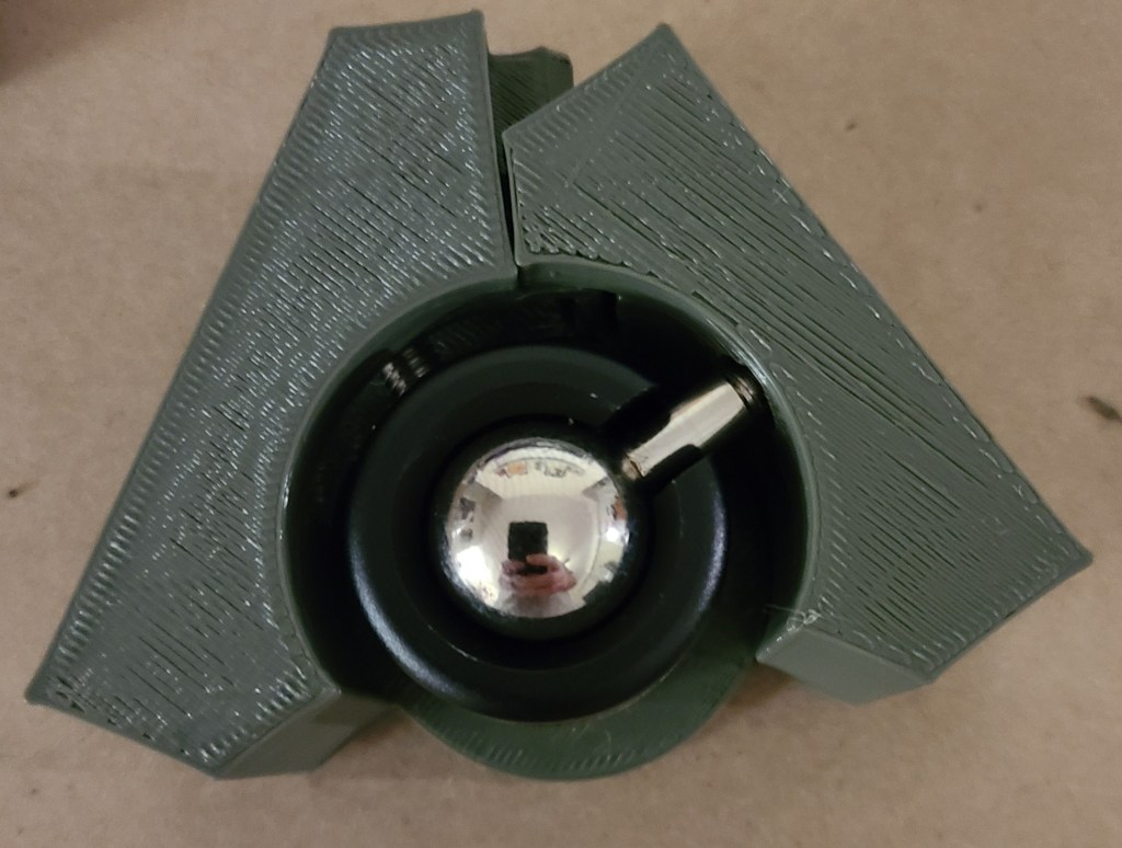
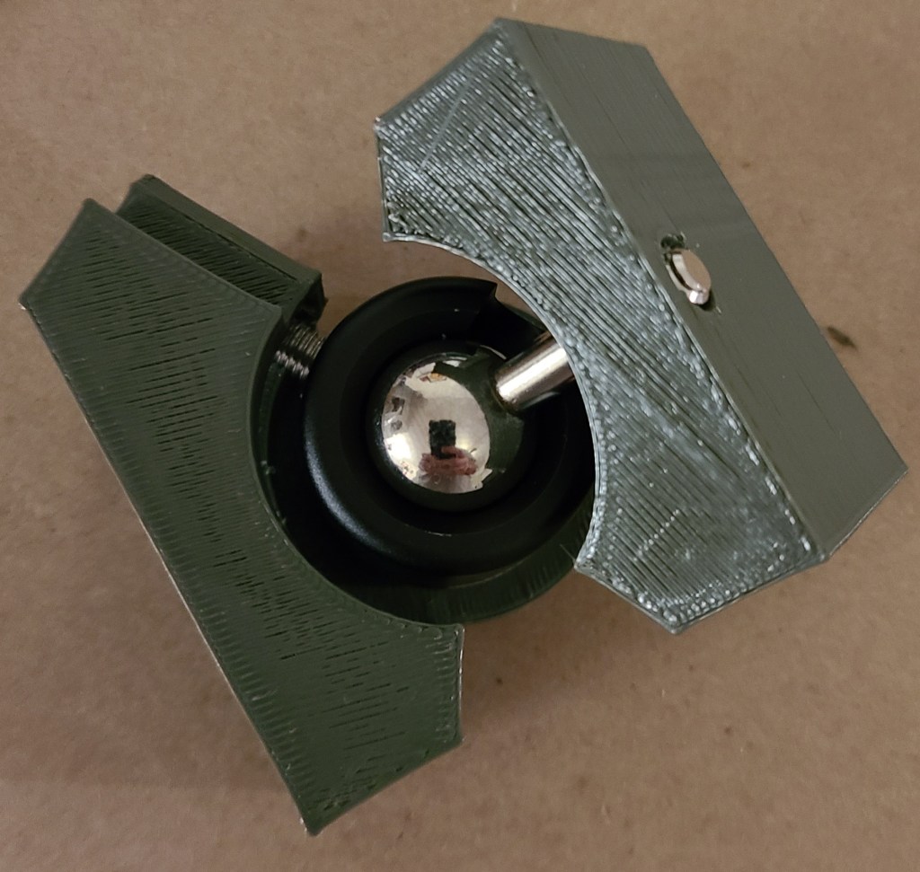
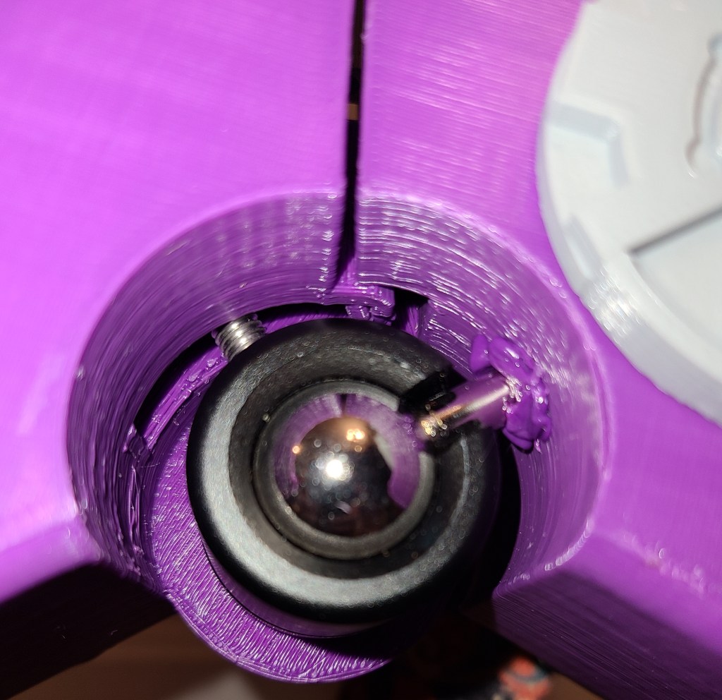
Ball Joint Design Tests:
This is the mechanical 3D printed assembly that I designed LAST, due to complexity. For one thing, I ended up having to get a new tool to figure out what the heck the threads were on the bolts on this thing.
I had designed the connections with adjacent sections as I was going along. This took a couple iterations to get close enough, but as previously mentioned, the bolt broke through the end stop, which I repaired with a 3D printing pen. I also had some difficulties with the screw going into the monitor joint. I appear to have made the hole for the heat set insert slightly too large and it slipped around. 3D printing pen to the rescue again! I covered the back of the screw and filled the area around the screw with plastic.

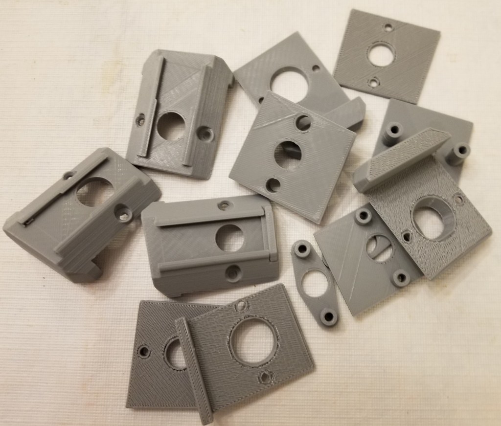
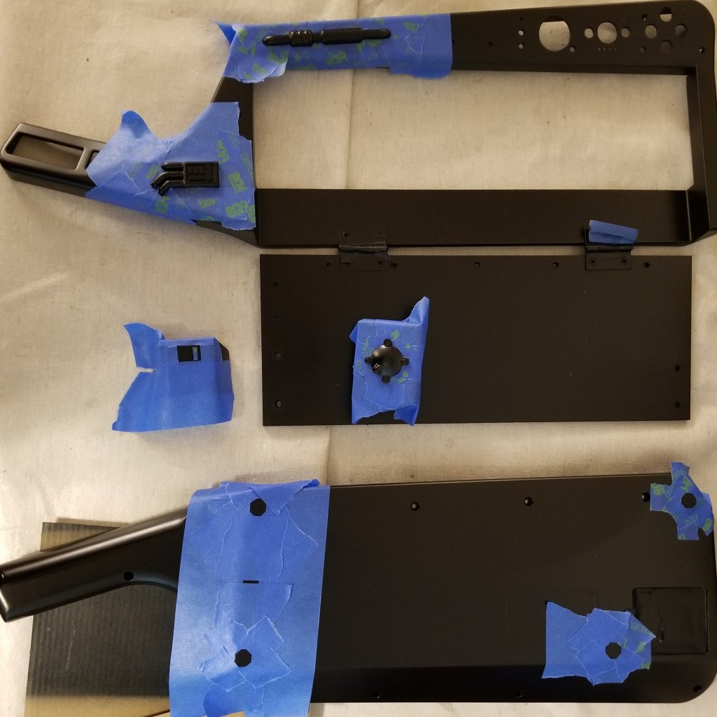
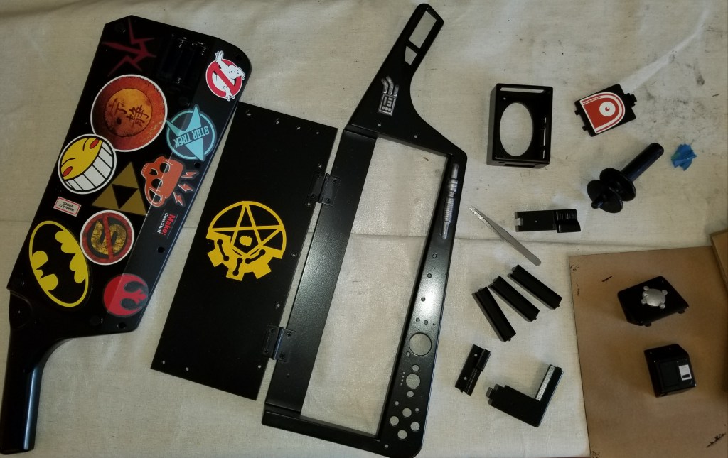
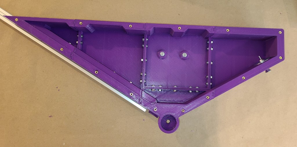
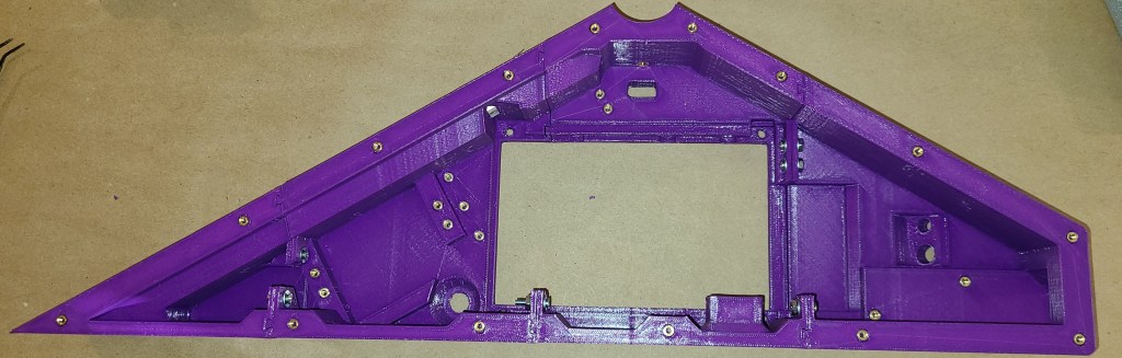
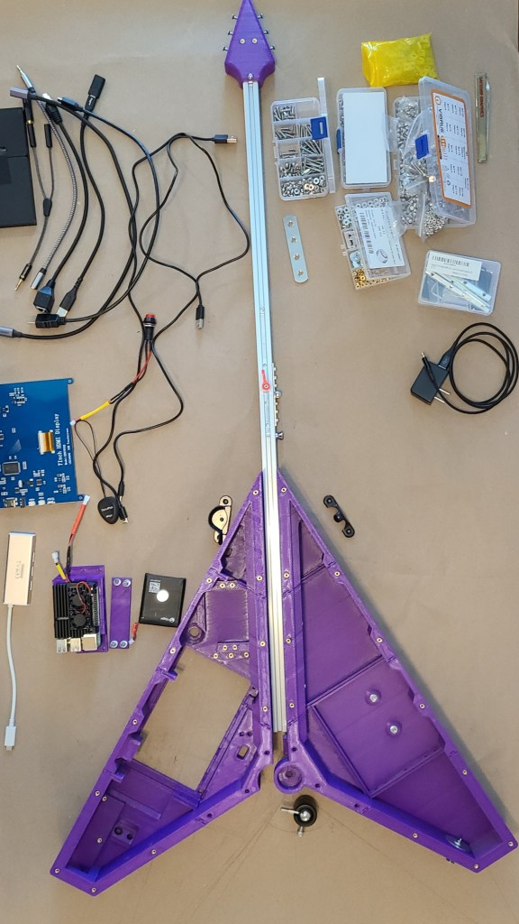
Full Plastic Assembly Layout:
Assembly required connecting all the appropriate plastic pieces together with bolts, then sliding the neck into the slot on the keyboard half and tightening the t-slot nuts. The picture below isn’t fully assembled, but shows about where things went. In particular, the neck is upside down relative to the position of the boards it’s supposed to connect to, since i needed to see the insides of the case for planning purposes.
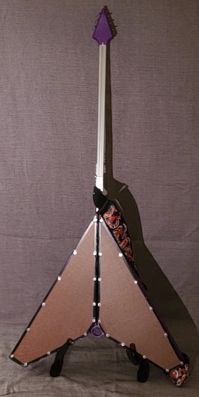
Hardboard backing:
In order to save a lot more 3D printing time and hopefully add some rigidity, I designed this with a board backing. Scored and snapped hardboard.
I didn’t photograph this very well, as I was kinda in a hurry to finish at the time. I cut hardboard to fit the back, drilled holes, and wrapped the edges with electrical tape for a slightly neater look than the edges of scored and snapped hardboard. Down the line this needs to be painted or replaced.


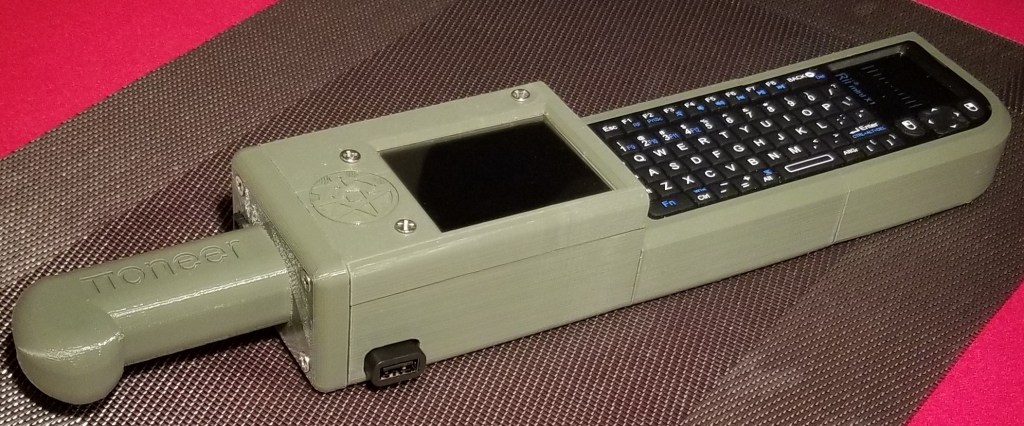
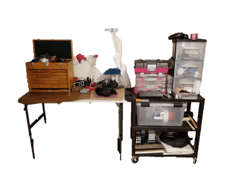
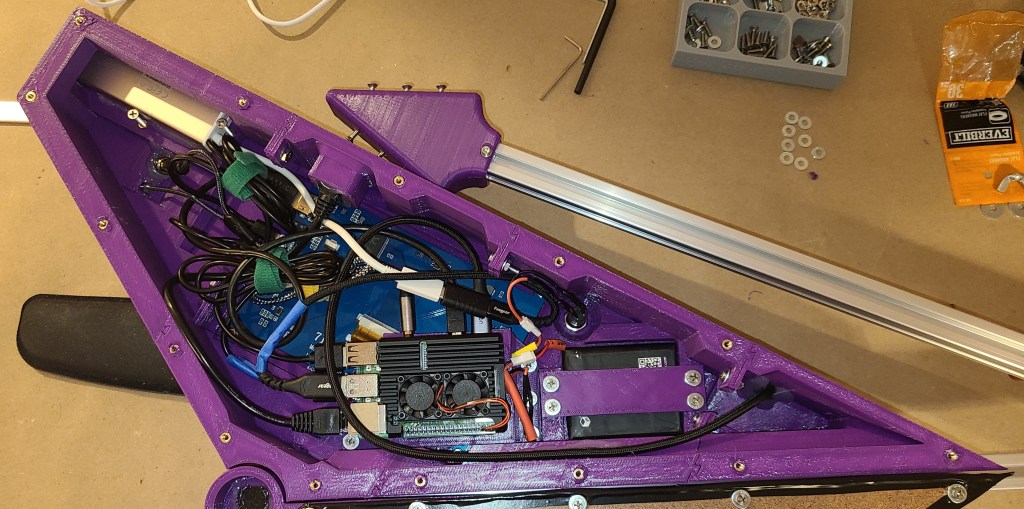
Monitor/CPU Internals:
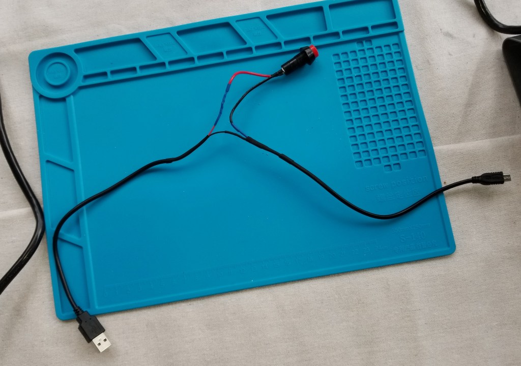
Here’s the setup overall. I added breakaway extension connectors for the battery and the power switch (I colorcoded them to prevent mishaps). The USB cables mean to go to the USB 3.1 connectors are wrapped in blue tape.
Some parts were hot glued into place, as I can remove hot glue with a bit of effort if I need to make modifications later. Also, it allowed me to get away with not having positive retention on the audio jacks, which would have been a pain to implement on the short timescale I had available.
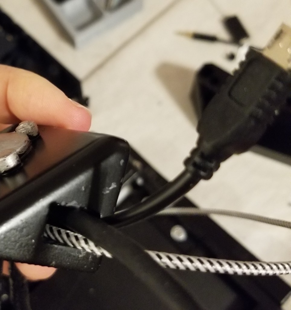
Here’s the modification I made to the PiSugar2 Pro battery management board in order to add an external switch that I could get to more reasonably. It seemed to work at first, but for some reason it no longer seems to work, so for the moment I’ve bypassed this board and only try using it directly plugged into the Raspberry Pi.

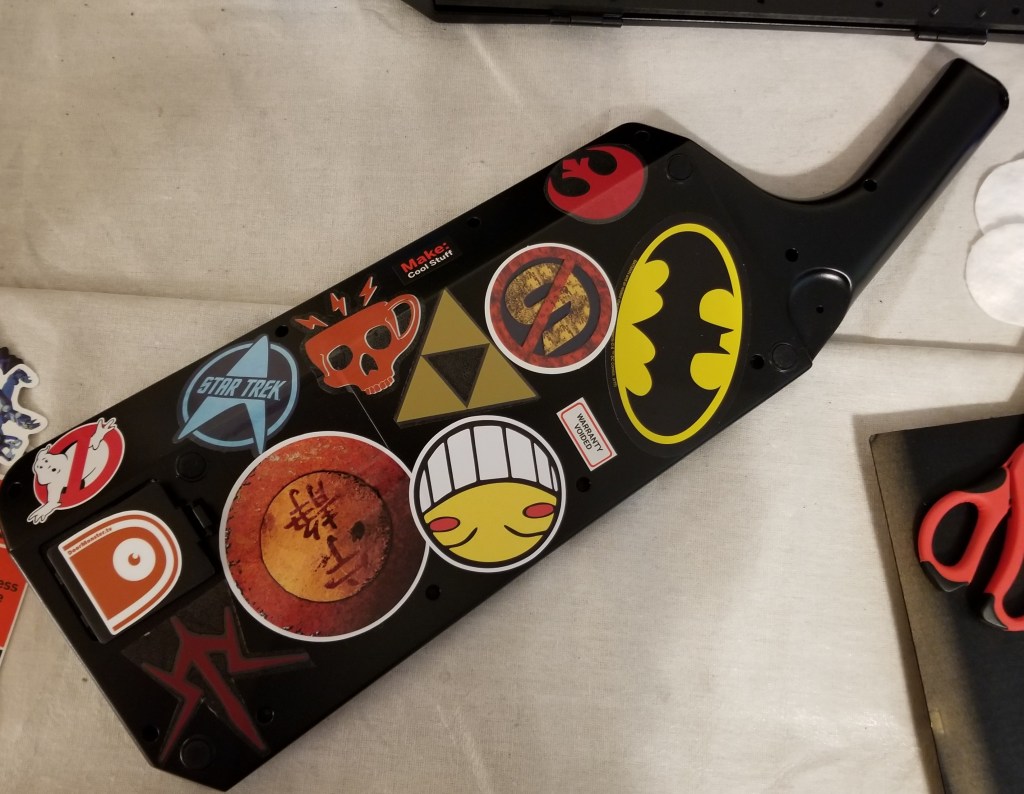
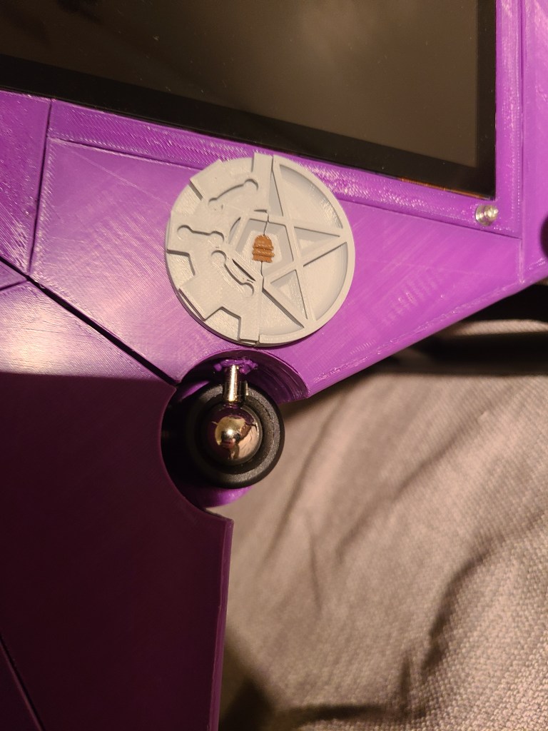
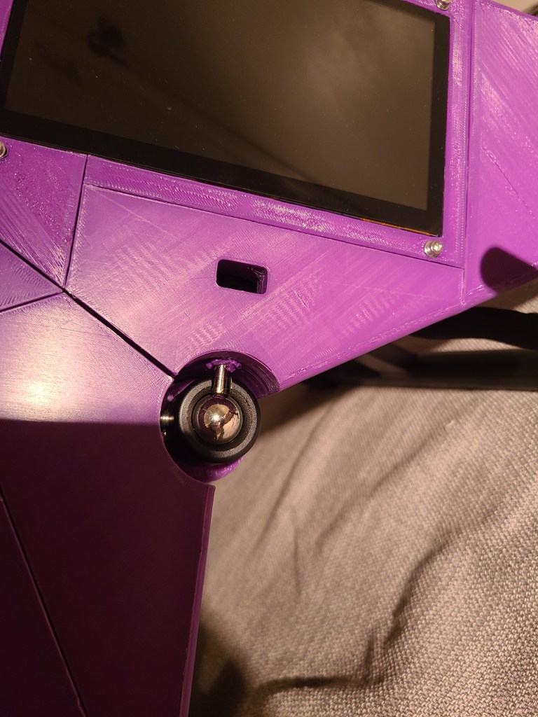
Upgrade Port/Cover:
Here’s where I placed and covered a spot for a potential USB upgrade, intended for a cable connecting the keyboard physically to the Pi for power and more reliable data. The cover is my maker coin, modified. The door in the middle of the cover conceals a hole that the two halves of the coin are designed to wrap around a USB cable. The whole thing can be removed for a larger hole, big enough to run a USB cable through.

Whew. I’ve probably missed some stuff, and may need to go back and edit, but this should cover the vast majority of the build.