
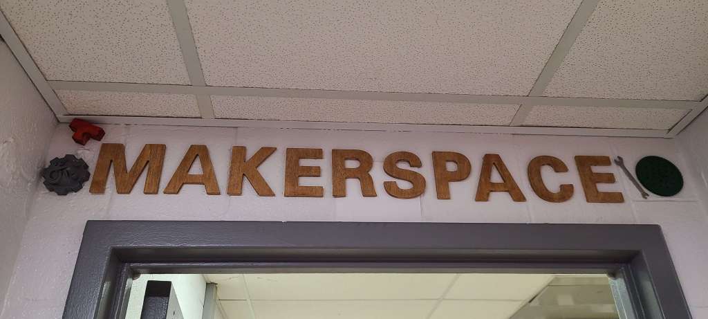
This took a little bit of searching and a couple days or so of printing, but I decided to make my classroom’s makerspace sign more interesting. I removed the wooden letters and replaced them with 3D printed letters. The reason it took a bit of searching was because I wanted every letter to be a different style than all the others, just to show some different things that 3D printing could do, and inspire thoughts of different things that could be made.
And in case anybody was wondering, the wooden letters aren’t going to waste, I have plans for them. Also, apparently because they were wooden, someone thought I was running a woodworking shop in there! I wouldn’t mind… it’s just not what we have going on in there. What was the phrase? Always be branding? I think having 3D printed letters gives a more accurate impression of the room.
Category Archives: 3D Printing

Classroom Workbench Organization
When you spend 10 minutes looking for something and it turns out it was EXACTLY where it was supposed to be… just at a weird angle with a little stuff on it obscuring it… you get frustrated and finally make an organizer for it. Now I can find my 3D printing spatula every time. And the related tools.
I also decide that while I was at it I was tired of my hot glue sticks being kinda scattered. So here’s what I’ve been making lately.
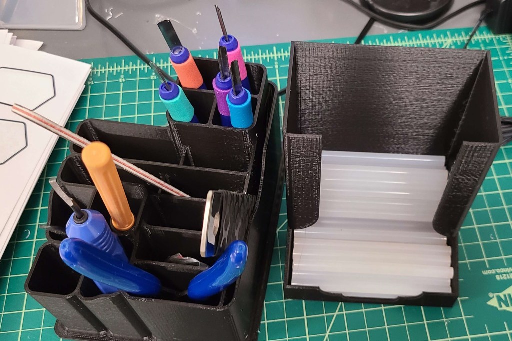
I can see all of them at a glance and grab them. I just have to make sure that the final location for the tools organizer is where the chisels aren’t in a spot anyone is likely to bump into. Normally I’d have everything sharp pointed downwards, but I can’t see the tips that way. Previously I kept them in a case, but there wasn’t a spot for it here. I might have to find another iteration for longterm storage of those chisels.

Makin’ and Decoratin’
Once I got enough room to breathe in my teaching, I decided the room needed some more decorations to make it a more inviting space. Especially since students had commented on the lack of wall coverage. Many classrooms have a lot of brightly colored posters and decorations to make the kids feel welcome and to pique their interest.
For a lot of it I started with a robotics theme, given that it was an easier-to-visualize subject than “design & modeling”.


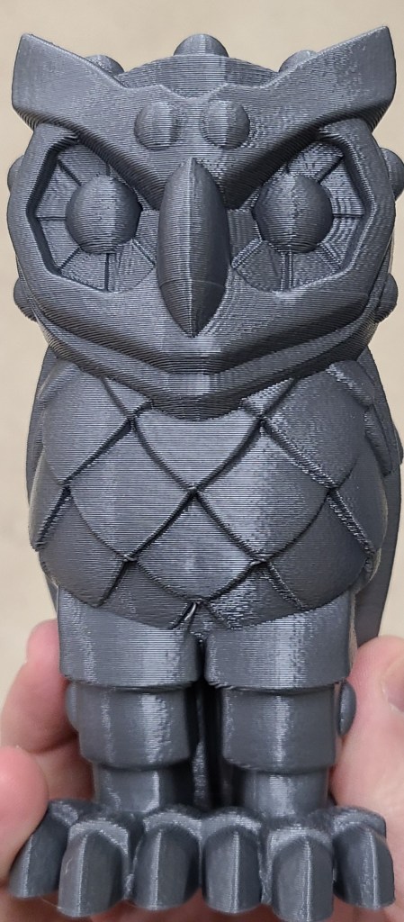
I also spent some time coming up with some examples that demonstrated more of what 3D printing is capable of, as well as some models that may come in handy when I cover 3D printing in more depth. Some of these were unusual shapes, others were versions of common calibration models used for tuning 3D printers.


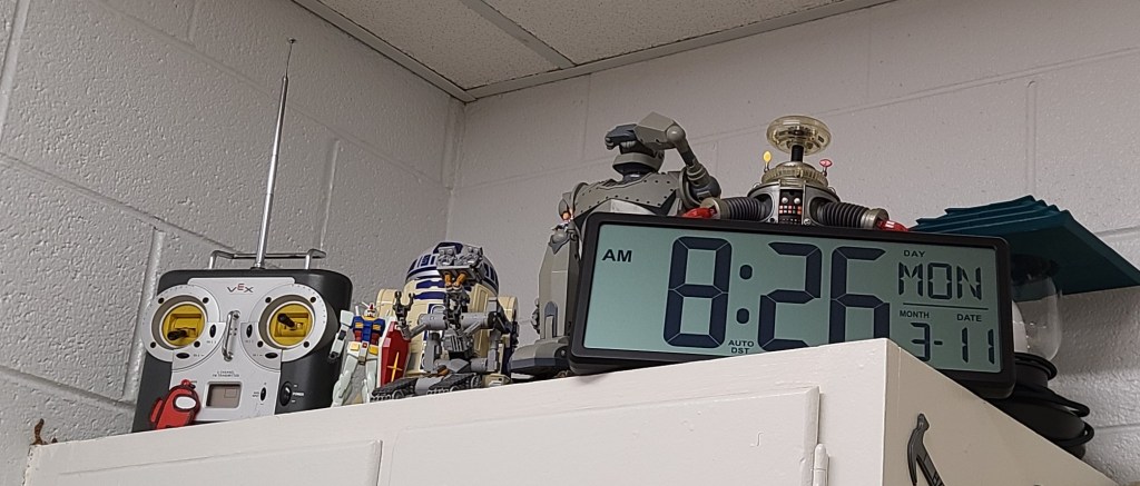
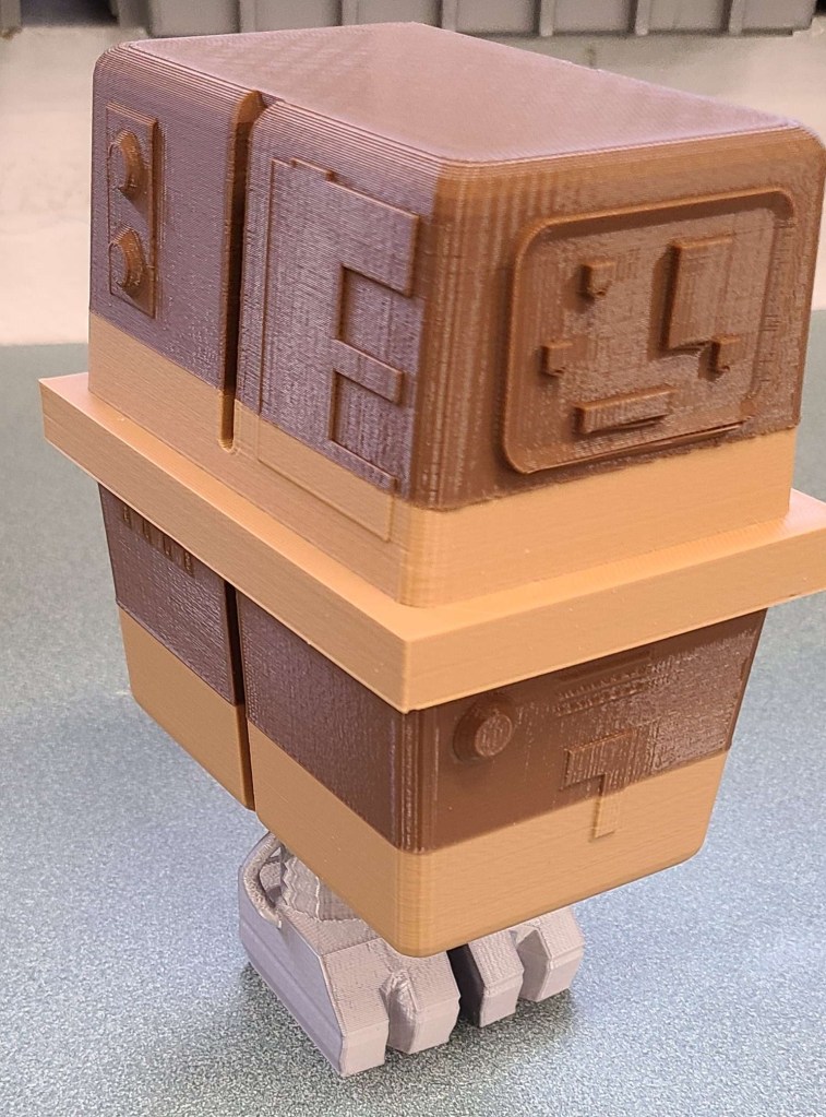
Some items were for establishing the theming of the room as a place for general Making.


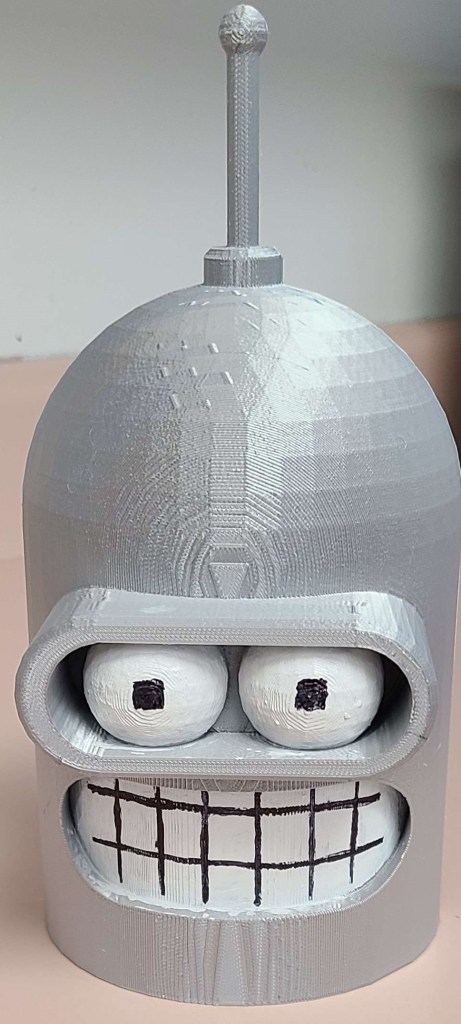
Based on some conversations with students and learning some of the pop culture things that they were into, I also added some other decorations to catch their interest and demonstrate some things that could be done with the 3D printer and a little coloration.


I am always trying to add to the collection, and hope to inspire the next generation of Makers. I want my room to be an exciting and welcoming place for creativity. Having walls filled with color and variety seems to be helping set a mood for my students, and occasionally I challenge them to figure out what I have changed recently. It is fun watching their eyes light up and their excitement when they realize I’ve added things they recognize to the room.

Classroom Makerspace Signage
Once I got some time after the initial rush of my first semester, I’ve done a bit of decorating to set the tone of the room and make it more inviting. I’ll probably cover some of the changes I’ve made over time, but today I’m focusing on a bit of signage for the room.
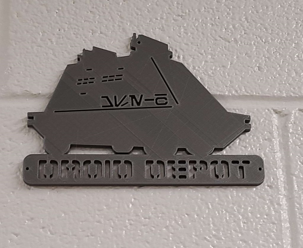
Before they even enter the room, I want people to know that it is a Makerspace, and I try to reinforce that with additional things within the room. I’ve made a display over the front door, and added a few things to set the mood.
The letters are from a dollar store, with a little bit of staining for color. The other items are things I have plenty of in the room.

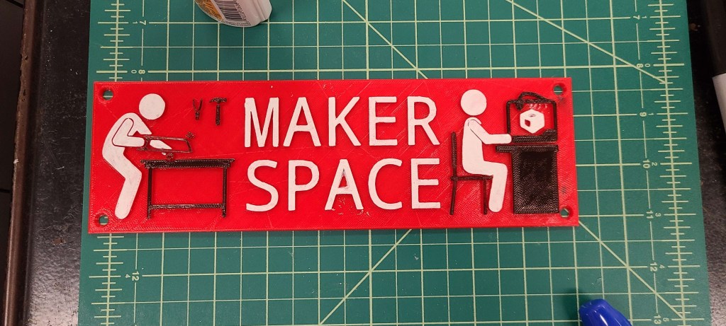
Inside the room I have included a 3D printed sign that also reinforces this (photo is from during creation). Printed in red, with a few classroom supplies to create color contrasts. Amazing what a difference a little sharpie and whiteout can make.

Screwdriver Stands
Sometimes you just get tired of having stuff laying around the workshop and getting in your way… and just generally looking like a mess. Side benefit of having access to CAD software and a 3D printer: it’s easy to design and print your own storage solution.
In my classroom I have several Warrior electric screwdrivers from Harbor Freight, and I got annoyed with laying them down on the counter to charge. It’s cluttering and frustrating, so I designed and printed some stands that link together.
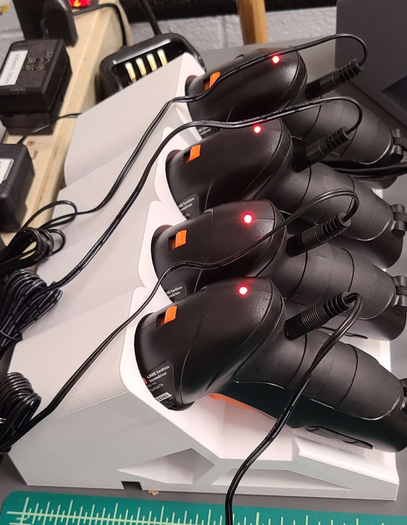

If you want to make your own, you can find them at the link below.

Back to tinkering
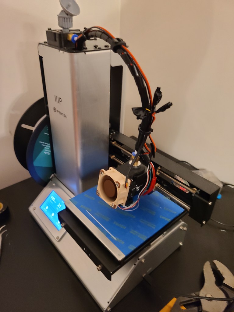
Things have been really busy the past few months, but I’m finally getting back to working on the 3D printer.
I’ve been splicing various premade models designed for previous generations of the Monoprice Select Mini into one that allows for a better hotend fan and a part cooling fan.
Next up is properly setting up the wiring, manual switch, and integrating it into the wire bundle for the hot-end. Then recalibration.

Random Updates 08/28
I’ve been working on a few things crafting-wise lately, none of them too major at the moment.
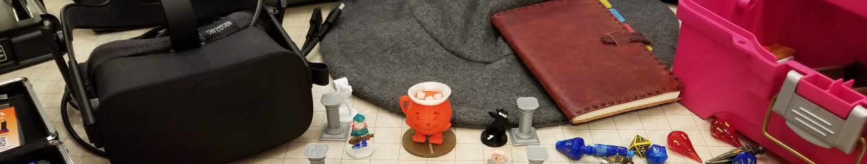
Minis-Painting:
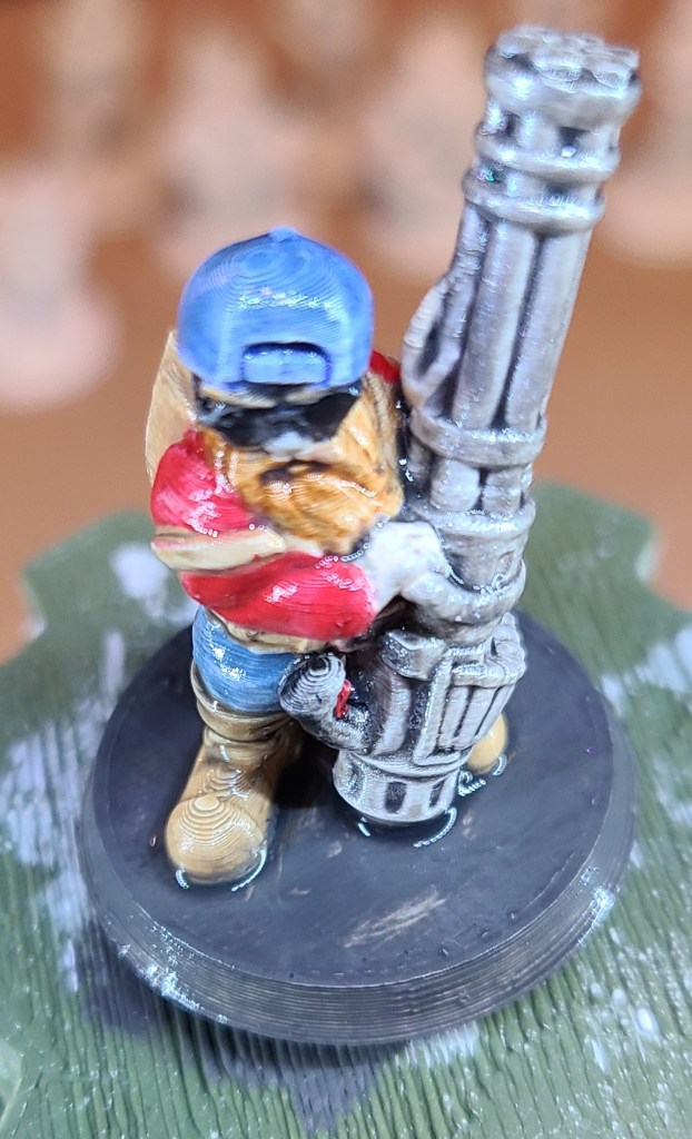
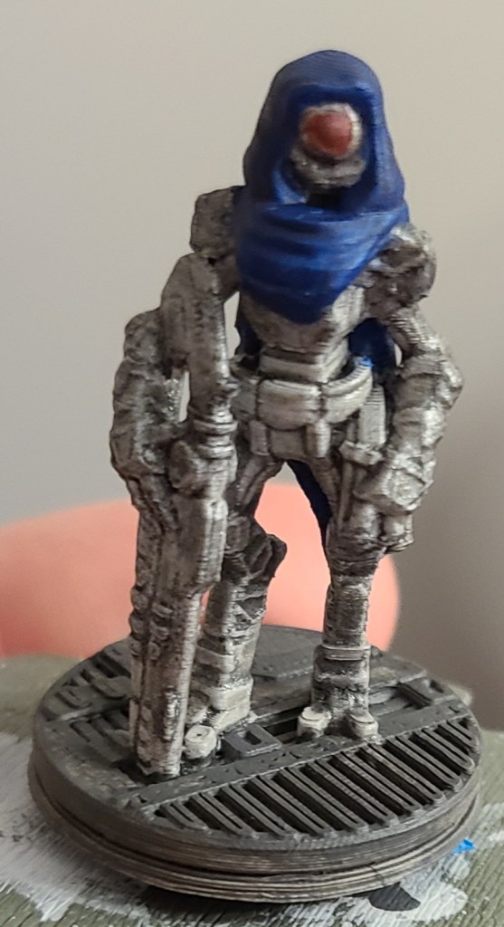
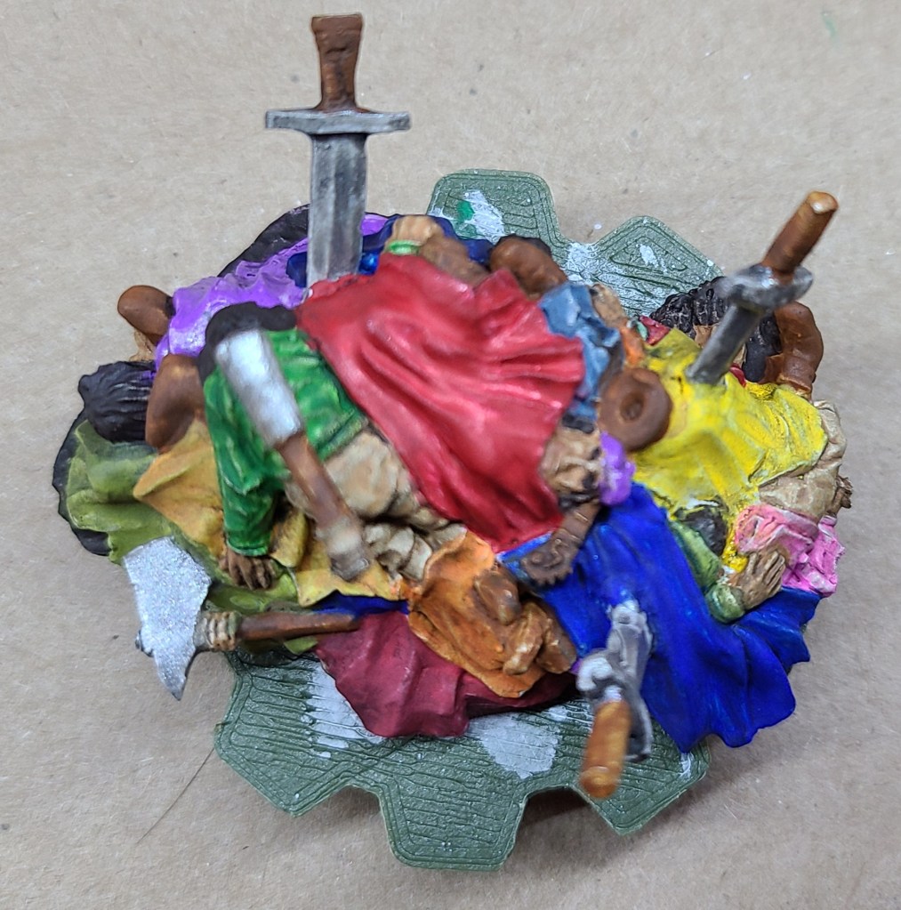
I decided to paint a few minis again. I’m hoping to print some minis for a game of Shadowrun soon, so while I’ve been tinkering with the printer I’ve been painting a few small things. A couple of minis that wouldn’t be out of place in-genre, and the Mound of Dead Bards from Gamers: Dorkness Rising. That last one took quite a bit of work.
3D printer tinkering:
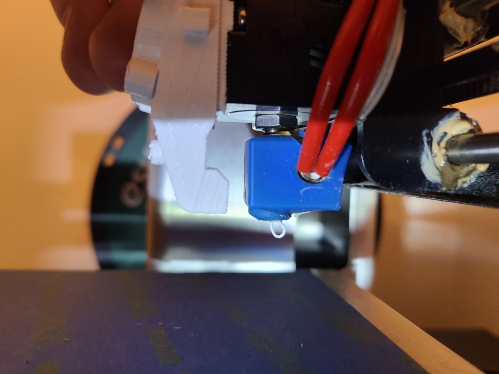
I’ve so far never managed to get the Monoprice Select Mini Pro to print minis as nicely as the other printer. I’ve been tinkering with some settings, and also with the hardware. Main thing I want to change is to improve the part cooling. I’ve gone through a couple iterations of air vent modifications and swapping in a better fan, but I really think it needs 2 fans. Unfortunately all the designs I see that include 2 fans are for different configurations or models, so I’m having to do some model splicing and editing. The main issue I come across is that the bed levelling/z axis sensor is mounted in a specific location not present on earlier versions of the MPSM, so I’m having to carefully splice that mount in in a way that is compatible with the air mods. I’m also doing a bit of experimentation with freehand modifications with the 3d printing pen, but the improvement has not been significant.


Bag of holding repair/upgrade:
I’ve had a bag of holding from Thinkgeek for years. Used it in my college days until I overloaded it with weight and damaged it beyond my ability to repair at the time. I’ve carried it with me from place to place, and occasionally used it (with some safety pins over a busted zipper or two) for thematic appropriateness or something “close enough”.
Recently I came across the bag again, and decided to work on it, inspired by finally going to a tabletop RPG night again. So far I’ve repaired the failed zipper, reinforced all the zippers, and added pull tabs on the zippers to make them open and close more easily. I repaired the fabric where the stitching had been coming loose, such as on the zippers and the strap where it attaches. Since I’m gaming in a high traffic makerspace, and I recall these bags being somewhat common, I’ve been adding patches to make it more identifiable. Most recently I decided to finally test out tge chemical NeverWet, and a “magic bag” seemed an appropriate use of it


I’m currently waiting on the neverwet to dry. I was able to use an old pressure fit curtain rod to hole the bag between two posts for spraying. Thankfully the fumes died down after a while. They were pretty bad, and got throughout my home, even though I sprayed outside.

Ghostbusters/Luigi’s Mansion Mashup: Final Polterbuster
So, it’s been quite a while since I’ve posted, and at this rate I’m not sure I’ll be finishing a detailed description of the design and construction process anytime soon, so I’m gonna skip ahead a bit. If there’s enough interest in explaining the portions that I’ve skipped past (or I make myself take the time) I may circle back and explain.
Anyway, here we go. Through a lot of tinkering with 3D models, learning how to perform photogrammetry, and some hands on work, I finally finished the polterbuster, so now I have my completed costume.
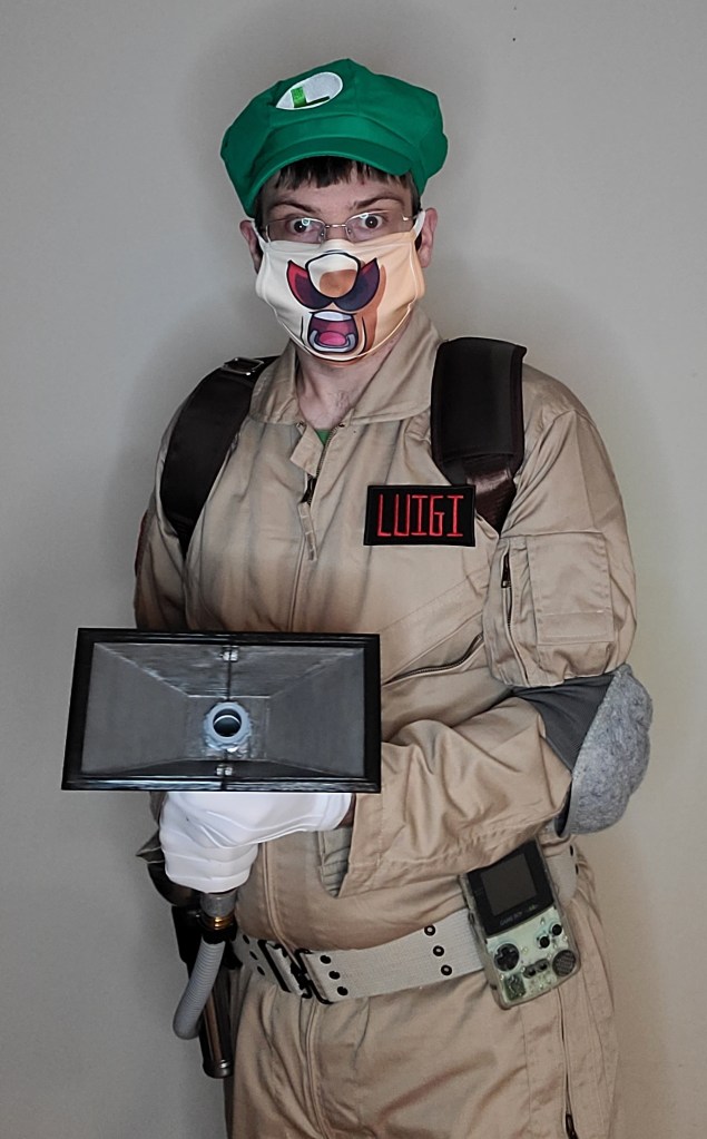
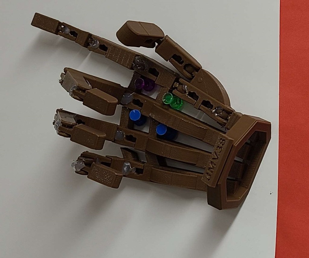
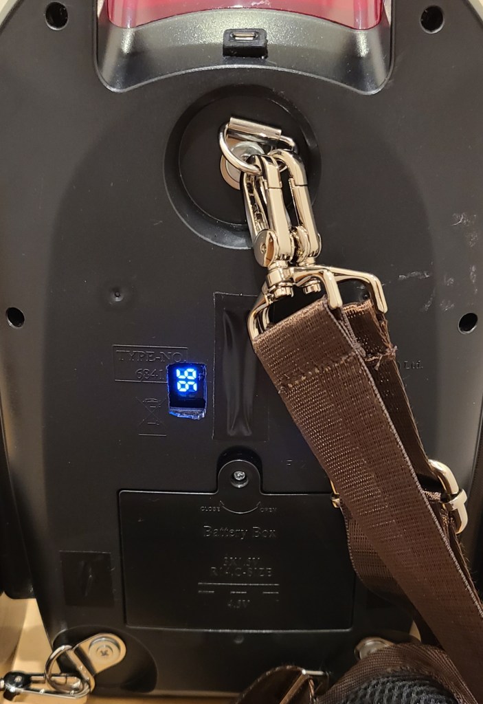
I got the hand unit to hang off the side of the pack on the custom made mounting brackets with some magnets. Haven’t yet gotten the straps to handle the pack being unbalanced with the unit on it yet.

And now here’s everything put together. It was finished just in time for Halloween… when there was nowhere to go. Oh well, there’s always the next convention!
Maybe one day I’ll revisit this and get some decent sound effects added to it.

PolterBuster Project: Lighting
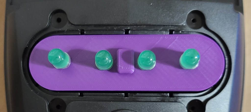
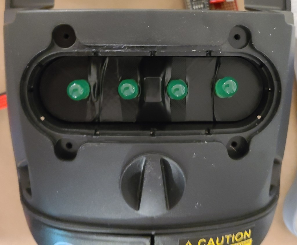
The clear compartment on the original vacuum contained a lot of white foam balls that got blown around by a fan when the toy was turned on. I decided that I was going to install lights here. The Poltergust from the games had one light… but this is an imprecise mashup piece. I decided to go with 4 lights, in homage to the proton packs, but green to match the aesthetic of Luigi’s Mansion.
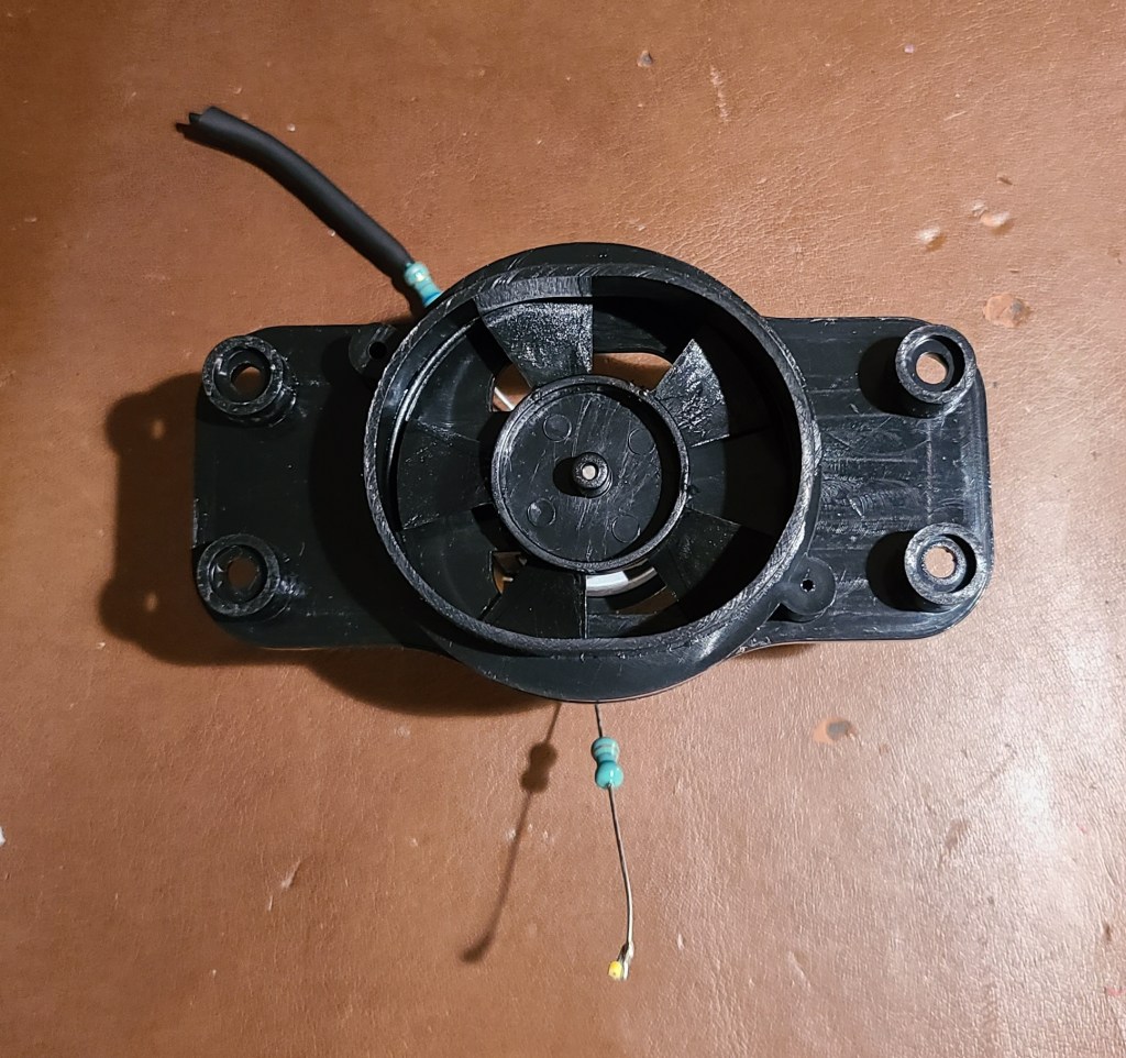
Here’s what I was working with:

I removed the foam balls, and originally I was also going to chuck the fan in the trash too, but I hold onto parts like that just in case, and I’m glad I did. This will be important for later.
For the lights I ordered some 10mm green LEDs (I like my tech chonky, especially for a cartoon character), and the accompanying resistors.

I 3D modelled and printed a piece to hold them into place in the spacing I wanted, and after a lot of frustration and soldering I got them into the installed. I put a solderless connector on the end so that I can separate parts when troubleshooting and/or if I decided to mount the board on the other half of the casing. I really need to spend some more time practicing crimping those connections correctly.

To control the lights for a blinking pattern, I used a knockoff arduino nano and modified some simple code for it. Gotta watch out for those knockoff boards, though. I had to go find special drivers so I could use the board, which can be nervewracking. You never know what people are going to include in code from an obscure website.


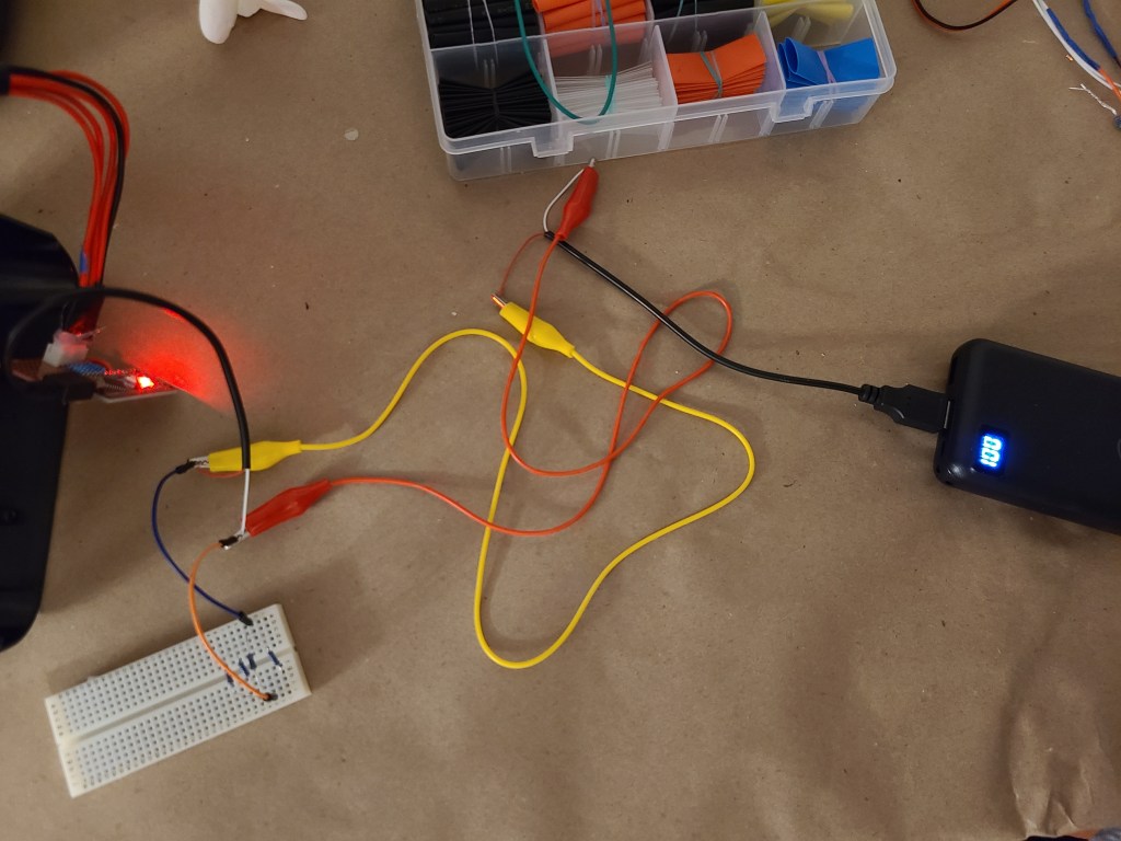
To power the board, I decided to use a phone power bank, as I hoped it would be an easy solution… I should know better.

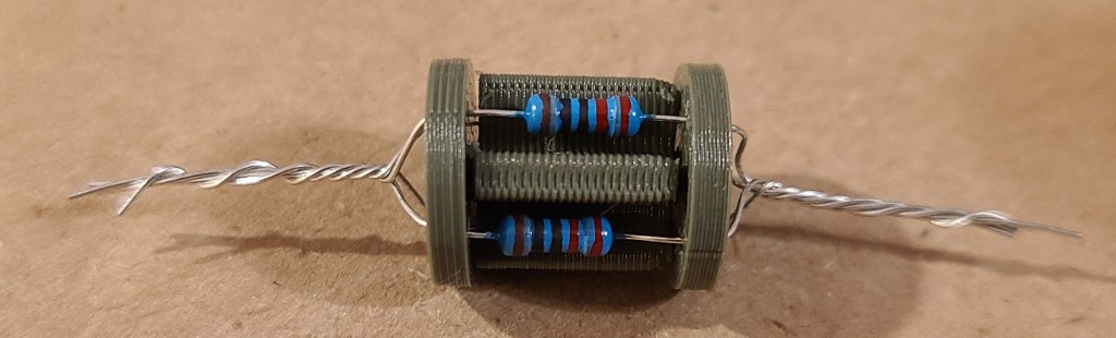
Hooking the board to the phone bank powered the lights…. for less than a minute. Then the power-saving features on the bank determined there wasn’t actually enough of a load on the circuit, and cut out. After a lot of fiddling with resistors, I added a bundle of 4 resistors in parallel to the circuit to add a little bit of load, which makes the power bank stay on.
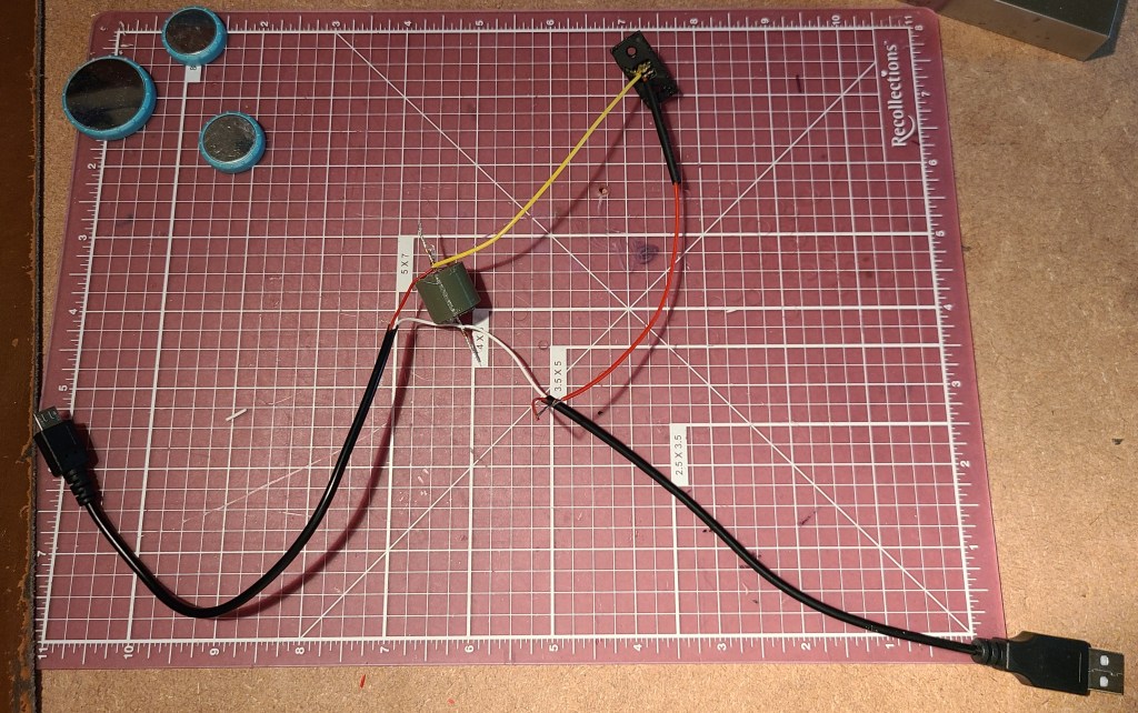
Once I had verified that the power bank would stay on, I went to permanently install the components. I continued cannibalizing the cable I was using, and wired the resistor into the circuit. I also added the toy’s original power button into the circuit as it would be a conveniently accessible button already built into the casing.
Of course, the one segment of the wire I HADN’T messed with turned out to have a short. I had to cannibalize another wire end to bypass it. (Not shown, just annoying)
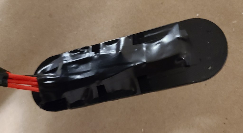
Then I had to figure out how to mount everything so that it would stay in place and function reliably. I went by my old standby for mounting things: hook-and-loop-backed command strips.
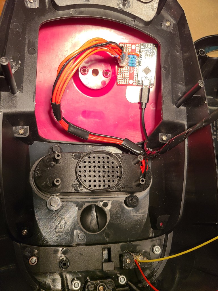
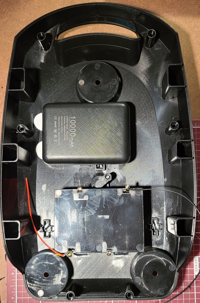
I used the modified USB cable to connect the two halves together for closing up. I also added an extension cable for charging the power bank without opening up the case, and a cut a hole for checking the display of the power bank to determine the charge status.
With that all wrapped up and functioning, here’s the light sequence. Pay no attention to the other changes for now.

Space Mouse and New Soldering Iron
I’ve been doing some training to improve my 3D modelling skills with Autodesk Fusion 360 (not sponsored, that’s just what I use) lately, and in one of the videos the instructor mentioned that he happened to like using a 3D mouse to rotate the models and help his workflow be just that bit easier.
Around the same time, someone happened to drop this link in the cyberdeck discord chat.
https://www.instructables.com/Space-Mouse-With-Arduino-Micro-Fully-Printable/
It’s the instructions for a homemade spaced mouse with 3d printed casing. It uses a small arduino board and some inputs (buttons and a clickable joystick) to make a space mouse.
Hmm… I can build a space mouse for a fraction of the cost of one I could buy? I get a new device for my workflow AND a project to practice a bit more with electronics and code?
Well, that’s a no-brainer. Project ahoy!
So, I started following these instructions, and built my space mouse.
Side note: every time I use the term space mouse I think of Mickey in a spacesuit. I don’t know if anyone else has that issue, but I just had to share.
I don’t think I’m gonna get too in depth covering it, as that feels redundant with the instructable above. I will point out a few things form my experience though.
This project made me very glad that the arduino boards came in a multi pack. I botched the first attempt HARD.
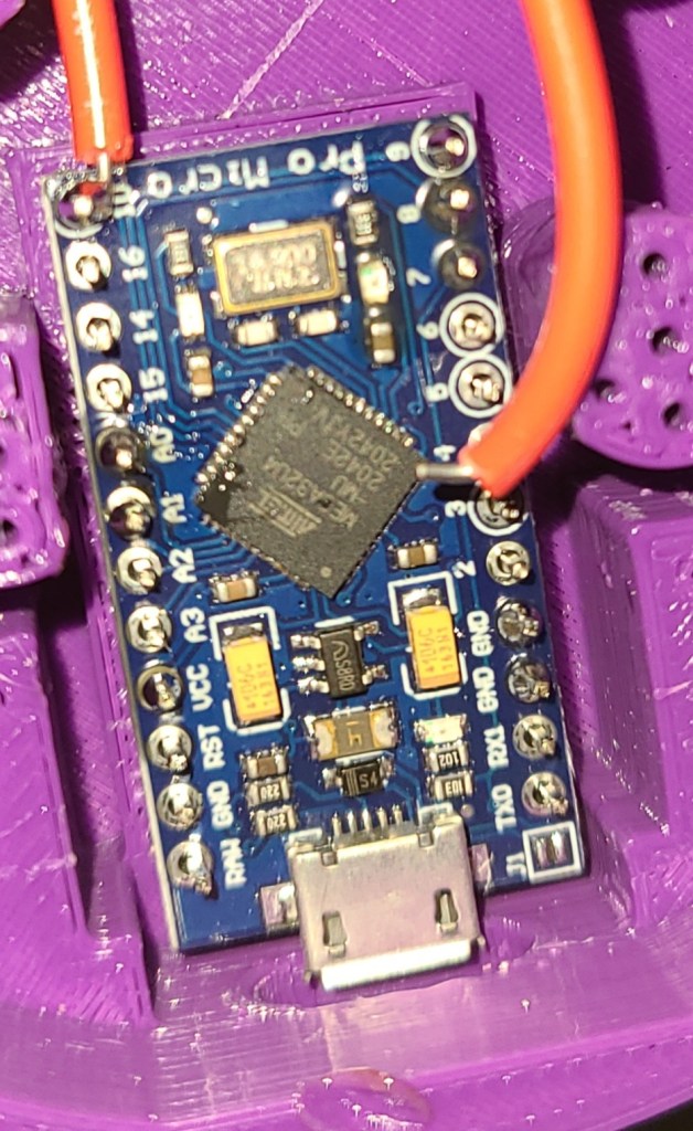
I put pins along the entire length of the soldering locations. Where are the wires supposed to solder to if you’ve put pins in all the holes? WHERE???
Turns out I wasn’t reading the instructions closely enough.
In addition, I was attempting to solder things while the board was embedded in the case. That didn’t work to well either. There was nowhere for the iron to really fit. While I was at it, it reminded me that I was using a very cheap soldering iron that I had only bought for something to do heatset inserts with, which wasn’t as precise or controllable as I needed.
So, with all that, I decided to make a few changes to my process and equipment.
1. I reprinted the case. I’d… kinda melted the board into the original case already and couldn’t get it out.
2. I carefully reread the instructions, found a diagram of the pinout for the board, and made myself a detailed diagram to work from before soldering ANYTHING.
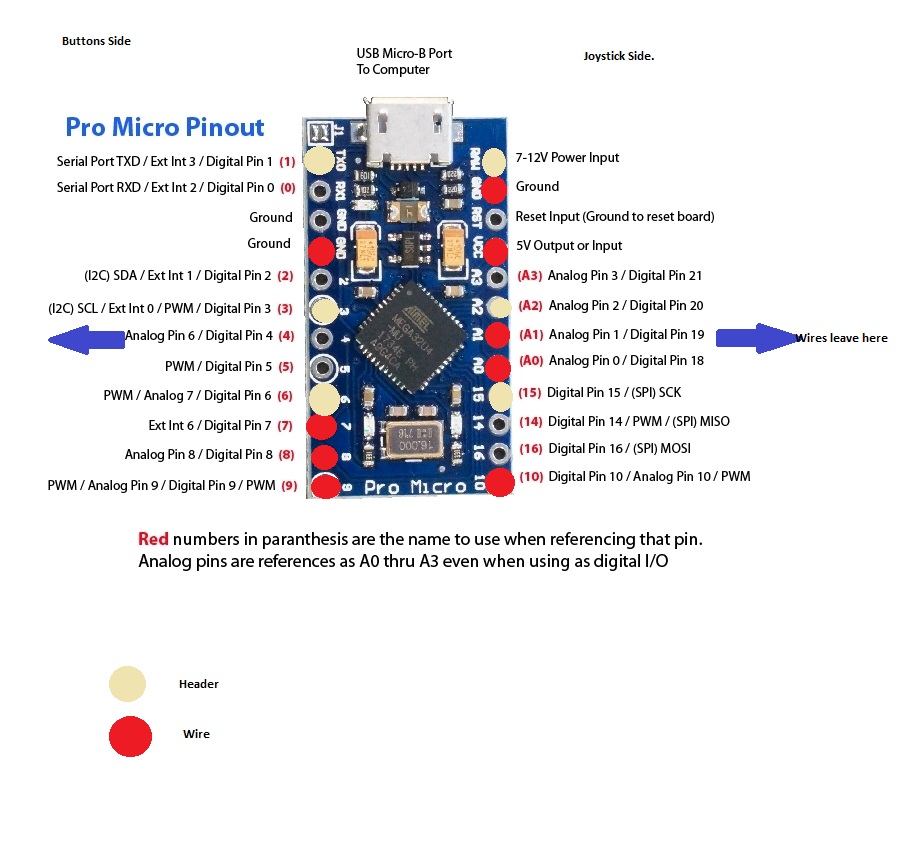
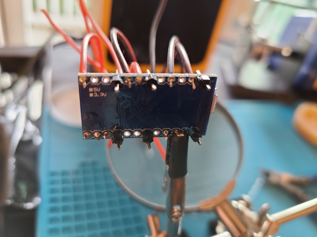
I only needed a few of the pins that came with the board to make things to mount the board to the case, not the entire row.
3. I used thinner, more flexible wires. The originals were waaaaay too inflexible to fit where I needed them.
4. I did all my soldering away from the plastic, then carefully installed the parts in. No unintentionally melted plastic.
5. I improved my soldering equipment and process. I made liberal use of solder flux (I’d shied away from it in the past), added a fume extractor to avoid having to work with the door open, and got a much better soldering iron after conferring with other makers about their recommendations. It was my third iron after all, it was time to get something that would work well. Finally got myself a Hakko.

Also took a little bit of time to do some reading/viewing so I’d take better care of this iron and have better soldering results.
This was a series that helped me, by the way. Sometimes you gotta go back to basics… and realize your bad habits that you’ve gotta fix.
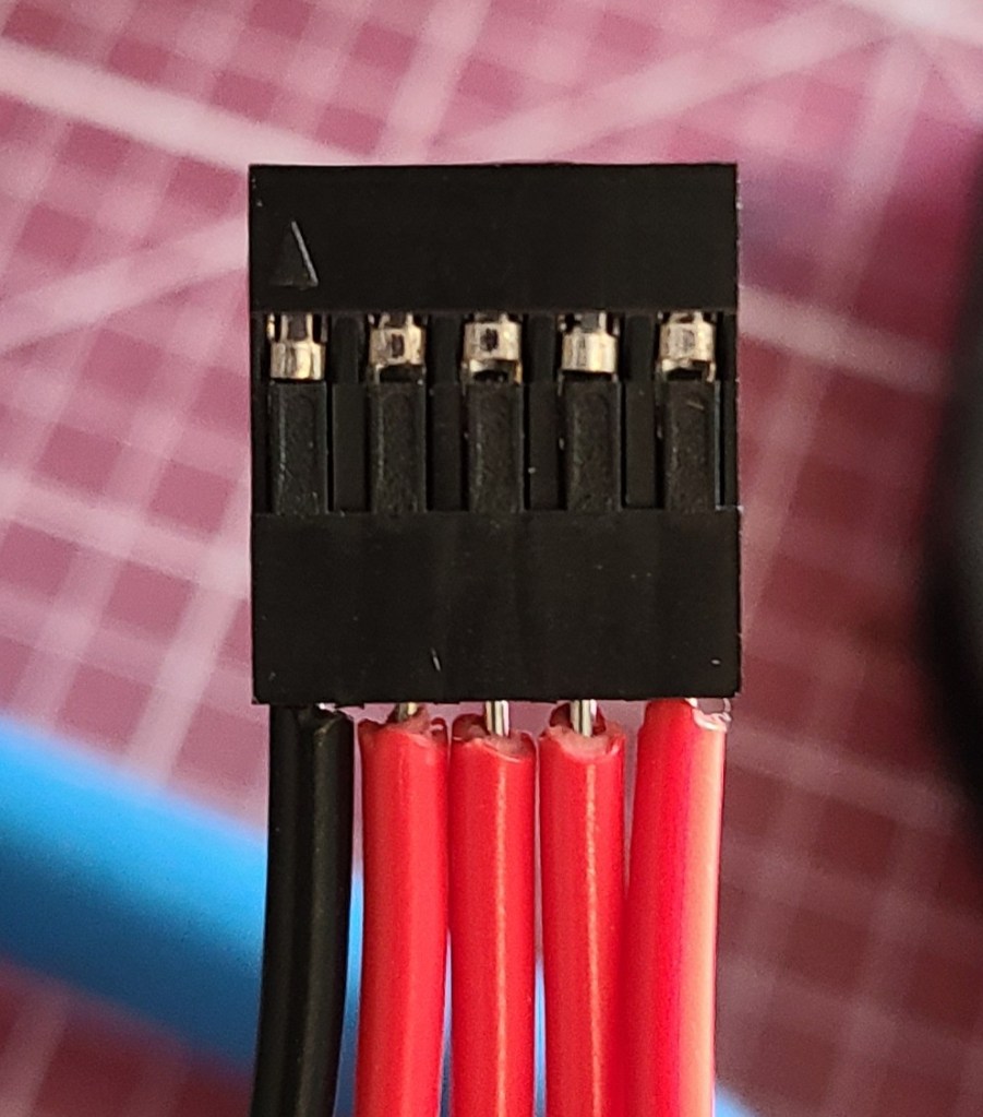
6. For connecting to the joystick, I used solderless connections to save my sanity, since it came with connector pins on the stick already.
Anyway, after all that on the hardware side, I finally got the thing built. All the wires soldered, the thing assembled and closed up.

I used black for the optional button extensions because I thought it’d be easier to use with contrast.
I ran into an issue with the thing slipping around on my glass desk, so I pulled out the rubber tape that I used for my arch lamp to make this nonskid as well.
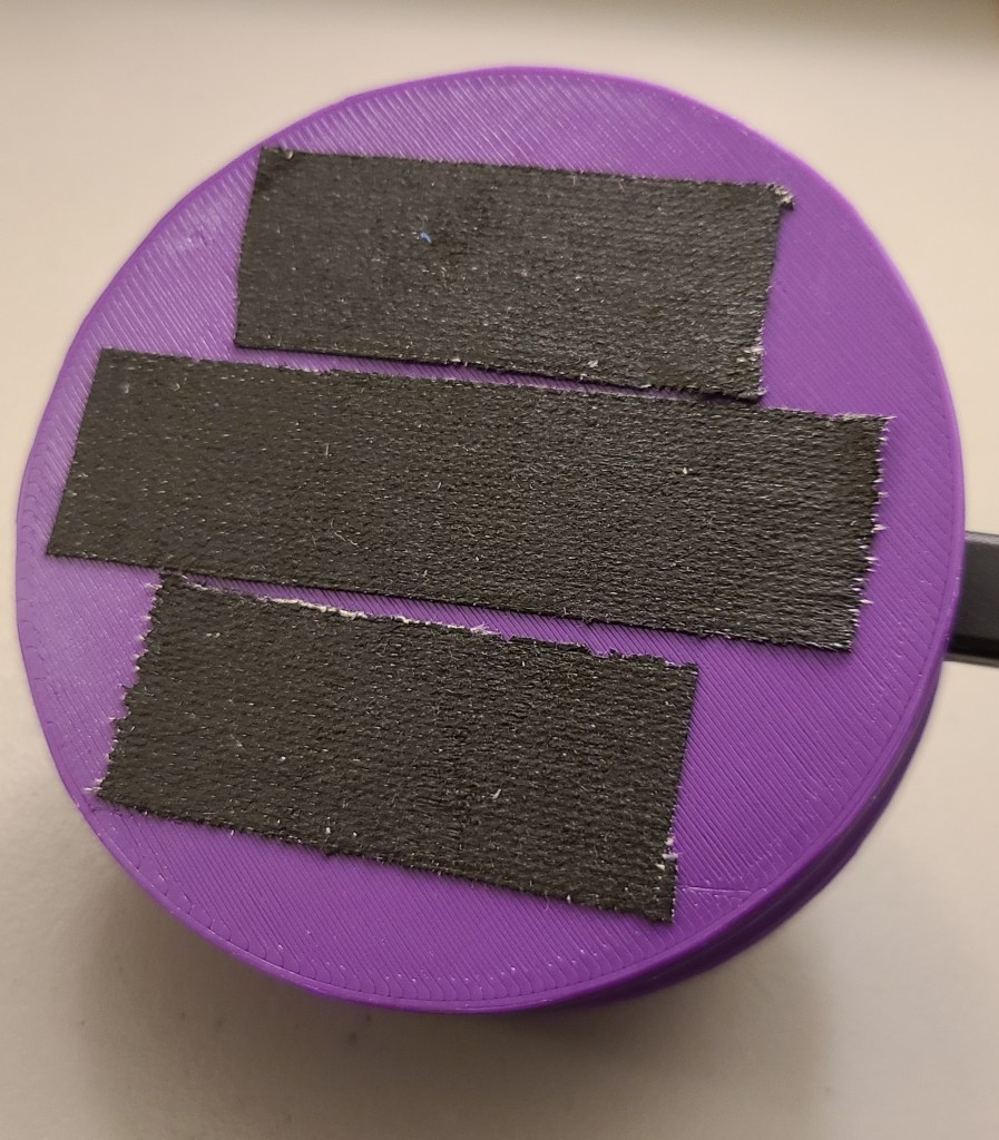
Now it doesn’t move anywhere unless I deliberately pull it off the desk.
Once I got the thing assembled and plugged up to the computer, I loaded the code included with the instructable.
Buuuuut…
The code was written primarily for this thing to work with Autodesk Inventor not Autodesk Fusion 360. The shortcuts are different in those two pieces of software. It took a bit of reading (particularly looking up the shortcuts for Fusion, figuring out the Keyboard. h code, and the firmware itself), but I eventually got at least the ability to orbit (rotate the view around the models) and zoom to work.
… also kinda had to swap the X and Y axes in the firmware. I might have gotten those two pins swapped on install. It works now, though!
Once I’ve used it a bit more, and thought more on what commands I use frequently, I’ll have to take the time to reprogram the buttons to do something useful.
Anyway, I got a new toy, got some more experience on these kinds of electronics projects, and had a reason to finally upgrade my electronics setup to be something more useable. Win!
Note: Yes, I know that isn’t the common spelling for useable, but usable doesn’t look right to me, and IT’S A VALID SPELLING, DAMMIT.
[END OF LINE]
