
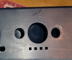
The casemod continues. As I mentioned last week, I designed a secondary cover for the Raspberry Pi. Here’s the Version 1 I mentioned messing up last week. If you look at it, you’ll notice that the main case has rounded edges, the secondary case has straight lines. This bugged me. I continued the print for purposes of fit check and everything.

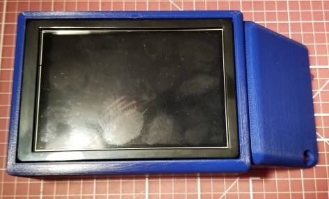
Below is what I’m going for with the case. You’ll notice the rounded edges to match the overall feel of the case. I’m actually not sure whether this is the version 2 or the version 3 of it in this picture, as the differences are not visible from this angle.
Here’s how it connects, btw:

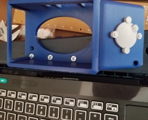
For comparison of the versions, I’ve added the pictures below. The main difference between the version 2 and the version 3 was that I forgot to include a very important hole.


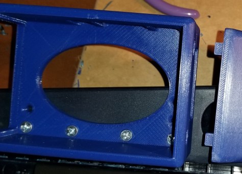
Going from version 1 to version 2 I had added a piece to fill the gap that had existed in the portion that was overhanging the edge of the case. I didn’t want stuff getting into the cover or into the case. However… that gap is where I had been routing the power cable, and I had forgotten to add a hole for the power cable to leave the case. So, pretty much the only change was adding a hole so that the cable could come out of the case. Now that I’ve done that, I took the time to drill the holes to install the case on the keytar. Here’s what it looked like.


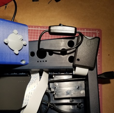
Note: In this last image you can see more of the Pi’s case exposed, despite me saying I was trying to seal up the case. That oval hole in the case serves two purposes, 1) to allow air circulation for the computer, and 2) I can carefully push the Pi out of the outer case if I ever need to access it or the screws underneath it.
I relearned a couple lessons in the process of drilling the holes that should have been obvious.
- CHECK THE BACK SIDE OF THINGS YOU ARE ABOUT TO DRILL. Especially when it’s into a case that you didn’t design/build yourself. There were some connectors for holding the upper and lower portions of the keytar itself together that I may have messed up. I did notice a few spots when I got partway into it that I very nearly damaged important pieces.
- CHECK WHAT STUFF YOU’VE REMOVED THAT YOU PLAN TO PUT BACK. There is a piece that originally held the buttons into the case that I will need to put back before I close the whole thing up, as it contains a few clear pieces that precisely fill in some holes on the case. I had to temporarily put it back in in order to drill another hole so I can put the screw for the secondary case all the way through later. I also discovered that I will need longer screws so that it (and some components to be printed/installed later) can pass all the way through.
Here is the spot I was mentioning in lesson 2. The holes to be filled in, the piece to replace, and what they look like together. It’s a really important part, especially since I’m trying to keep the case as closed as possible. Also, with those clear parts I might be able to put a light behind them later. I thought I was going to be painting before long, so I had removed it.


Anyway, at some point I decided that the case was a bit too plain, and could use a greeblie (I had to ask around to be reminded of the term for this), and what better greeblie to start with than the Universal Greeblie?
Adam Savage explains it well here. It’s fun learning these things as I go along!
The stl I used for the greeblie was from here:
Universal Greeblie on Thingiverse
The nice thing about it being a STL file is that I could make it any size I could print! So, I upscaled it, and this is the result:
I’m gonna superglue that sucker on later (it’s just held on by a bit of hidden tape for now) and then paint it with the rest of the case. I like the extra bit of detail, and I might have to find some more types of greeblies to install elsewhere on the case.
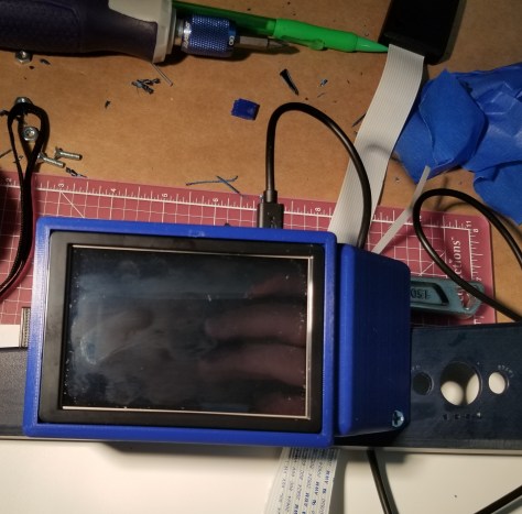
Before I forget, I added a little bit to the wiring, but it was mostly plug and play, so I almost didn’t include anything about it. I added a short micro-USB cable to the exterior of the case through one of the pre-existing holes, and a switch in-line between the power bank and the pi. I still need to figure out how I want to mount it, though I guess that depends on whether I keep this power system. It currently gives an undervoltage warning, even if I try to pass wall power through the power bank.
I also tried printing a small, angled SD card holder to fit inside the case (I plan on storing backup/alternate OS SD cards in the case)… but apparently the person who posted the model had scaled it up to be too big. I’ll have to find a new one, rescale this one, or create one of my own at a later time. It’s an internal detail that is subject to whether I decide to redo the power system, so it’s not urgent.
The Path Forward:
I’m still trying to get a a piece of material cut for the keyboard tray. Until that is done I can’t really start on designing the pieces to hold the keyboard to the tray and add the latches to hold the tray shut. I’m also not painting anything until I have most or all of the pieces so I don’t have to paint on multiple occasions.
I think the next thing on my list is figuring out how I want to design the holder for the SD card reader, and how I want to mount the power switch to the case.

This is a really cool build, i found it my searching for “cyberdeck” on thingiverse, Here’s the one i built https://www.thingiverse.com/thing:3857521
There’s a great cyberdeck discord group, you should check it out https://discord.gg/2yaSmC
LikeLike