
So, I was working on a few different aspects on this thing that aren’t entirely related, so I figured I’d split it up into the relevant topics. I still haven’t settled on a format for these blog posts, but I figured this would work for this update.
SD Card Reader Holder:
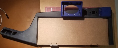
I designed and 3D printed a holder for the SD Card Reader, which attaches via screws to the case. Just for fun I decided to mix in the model of a floppy disk (3.5″ design, not the 5″ design) to indicate that it was where the disk was inserted. Kinda like with the secondary cover, I had to go through a few drafts of it to make sure everything fit and the holes lined up so that when I drilled into the original case I wouldn’t run into extra structure. You’ll notice that there are only three holes and the upper corner is cut off. This was done because there really wasn’t a good spot to put a fourth hole, and I didn’t want an extra corner sticking out from the case.


Sticker Order:
I’ve ordered a bunch of stickers to cover parts of the keytar case, wannabe rocker style. I’m keeping it to a theme of underdog/rebellious people from fiction, and with appropriate maker-themed stickers. The stickers are coming in piecemeal, but they are coming. Below is a list of the kind of things I was going for:
- Rebel Alliance (Star Wars)
- Black Knights (Code Geass)
- Serenity Logo (Firefly)
- Ed’s Smiley Face (Cowboy Bebop)
- Triforce (Legend of Zelda)
- Raspberry (Raspberry Pi)
I’ve considered loading multiple operating systems on to different SD cards, but for now this thing is primarily going to run on Pibian. I’ll label the appropriate OSes on the SD cards later once I spend more time installing them.
Tray:
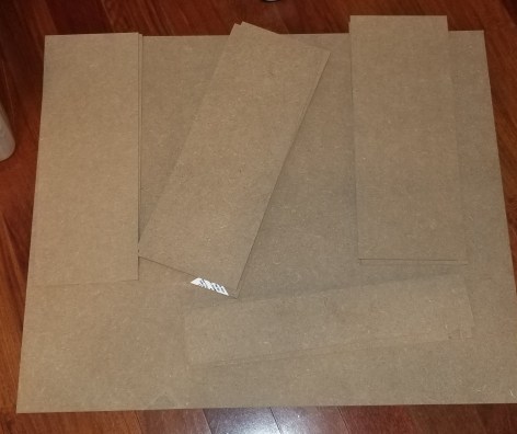
I finally found someone who could cut some material for me for the tray! I got them to cut several pieces of MDF for me to try different sizes for the tray, and to have spares in case I messed up the first time.
I’ve already attached the hinges, and the tray opens and closes fine.

It looks like since the screws were so long I needed to cut the screws shorter. My first thought was to cut it with my Dremel, but that throws off sparks and it was way too hot to be working on it outside over some concrete.

Me, preparing to use the Dremel… before realizing it was a bad idea. Safety first!
When it had cooled down some, I moved outside and cut one of the screws off with the Dremel. It was a pain, somewhat risky… and then I remembered I had lineman’s pliers, so I used that to cut the rest of the screws. It was a lot faster and safer than trying to use the Dremel. Not-a-pro-tip: I cut this thing while holding it inside a box, because I’ve had way too many things I’ve cut lately go flying across the room, and I didn’t want sharp metal objects on my floor.
I needed to wait until that is done before I take the measurements I need to fabricate the pieces that will hold the keyboard in place and provide a mounting point for the latch. I may also have to figure out how to add a handle of some sort to make it easier to pull the tray open, or else grab it by the latch when I need to open it. This is still on my to-do list.
Power issues:
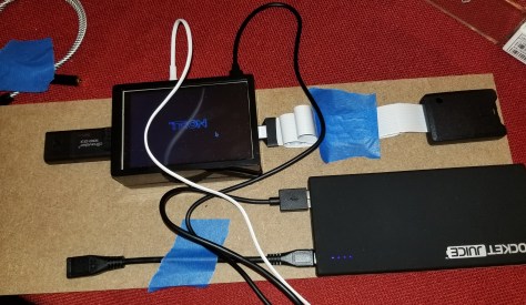
In the past I’ve tried two different power banks, and kept getting a low voltage warning. I decided to try another recommended approach from a book I was using for learning about Raspberry Pis, which recommended a case for 6 AA batteries routed through a UBEC, which I then routed through a connector to USB so I could plug in the switch that I wanted.

My attempt at custom wiring
That gave me the same result. I sent a picture of my wiring setup (the picture above) to an electrical engineer I know, and he commented that it was a lot of wire, with the resistance making what should be adequate voltage drop to inadequate voltage. I went back to trying the power bank, and a much shorter cable that didn’t include a switch… and now the Pi only intermittently shows a low voltage warning, instead of constantly. Mostly when I try to get online with it. So… it’s an improvement. Not perfect, but still better than seeing a warning constantly that the system is probably gonna be unstable. Downside of the new arrangement is that I’m going to either have to keep plugging and unplugging the wire to the Pi or else opening the case every time I want to turn it on. Here’s the components laid out for when I was trying actually doing something with the Pi.
Here’s everything inside the case as it is right now. The components are just in there loosely for now, but will likely be mounted with command strips for most parts, though the ribbon cable will likely be secured with painter’s tape.

Current Status:
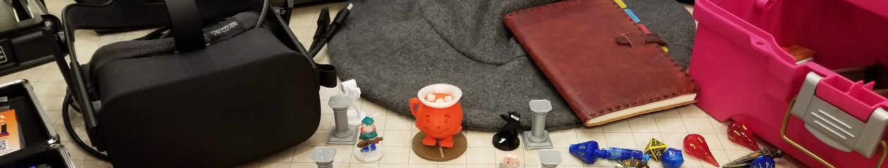
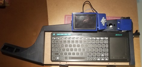
Here’s the whole thing as it currently stands, though I do take the components out while working on various parts.
- The power connection uses a shorter wire than before, and there is a short wire from the outside of the case (through a pre-existing hole in the case) to the power bank. I’d prefer to include the switch in the design, but that will/would require cutting and splicing the cable to the minimum length that can still do the job.
- I’ve routed an aux cable from the pi to one of the other holes to be plugged into speakers or headphones externally.
- The SD card reader has it’s own spot, and the ribbon cable routes through the space between the keyboard tray and the case, and back up through the secondary cover to the Pi.
- The tray functions on it’s hinges.
This thing is coming together, slowly but surely!
Upcoming plans:
I need to design and 3D print the mechanical interfaces between the keyboard, tray, and latches for the case. This is gonna take a while, because:
- The parts will have to connect to each other
- The top of the case, the tray, and the keyboard are all at different angles from each other, and all need to be correct to hold the keyboard and allow the latch to work.
- The pieces will have to hold the nuts to allow screws to come in from the outside.
- This will have to be in multiple pieces because my printer can only handle things up to about 4 inches in a given direction.
