Category Archives: Projects

New Process: Miniatures Painting

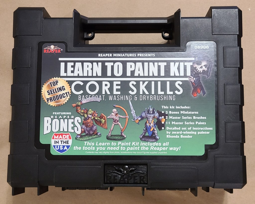
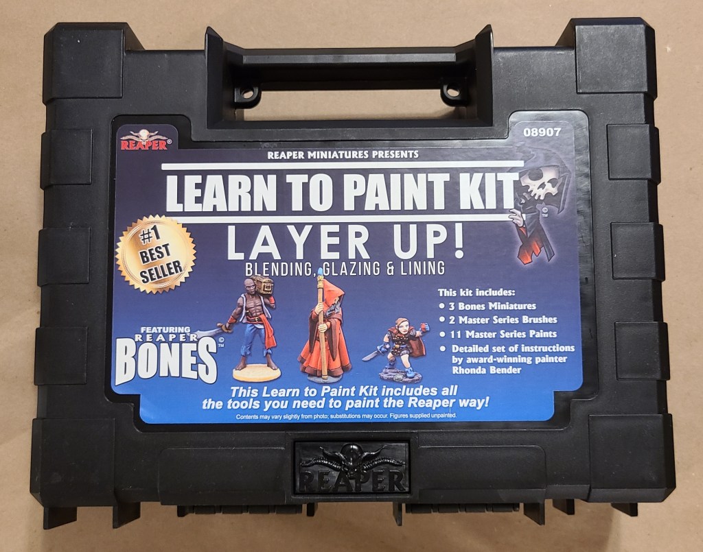
I finally got around to deciding to paint my 3D printed miniatures, so I needed to tool up and learn painting skills. That all started with a learn to paint kit, some brushes, and lighted magnifier glasses that I received as gifts.

This escalated quickly. I’m going to cover a lot of the things I’ve added or built on the setup here, because if I did it as individual Sanctum Upgrade posts they would stretch out pointlessly and my blog would be nothing but painting posts for the next few months.

If you want to see a more succinct form of this setup (whether out of impatience or for better reference), I’ve added a page for my current setup under Manufacturing Setups.

Direct link is here: Miniatures Painting Setup

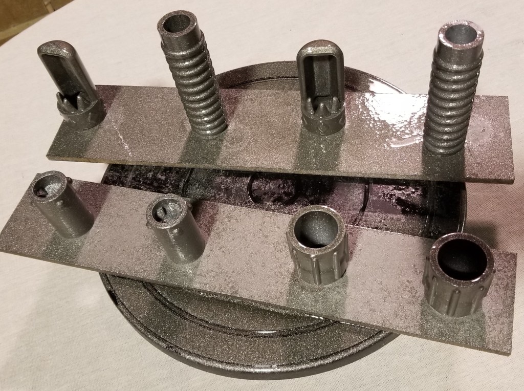
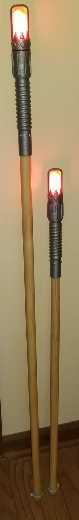
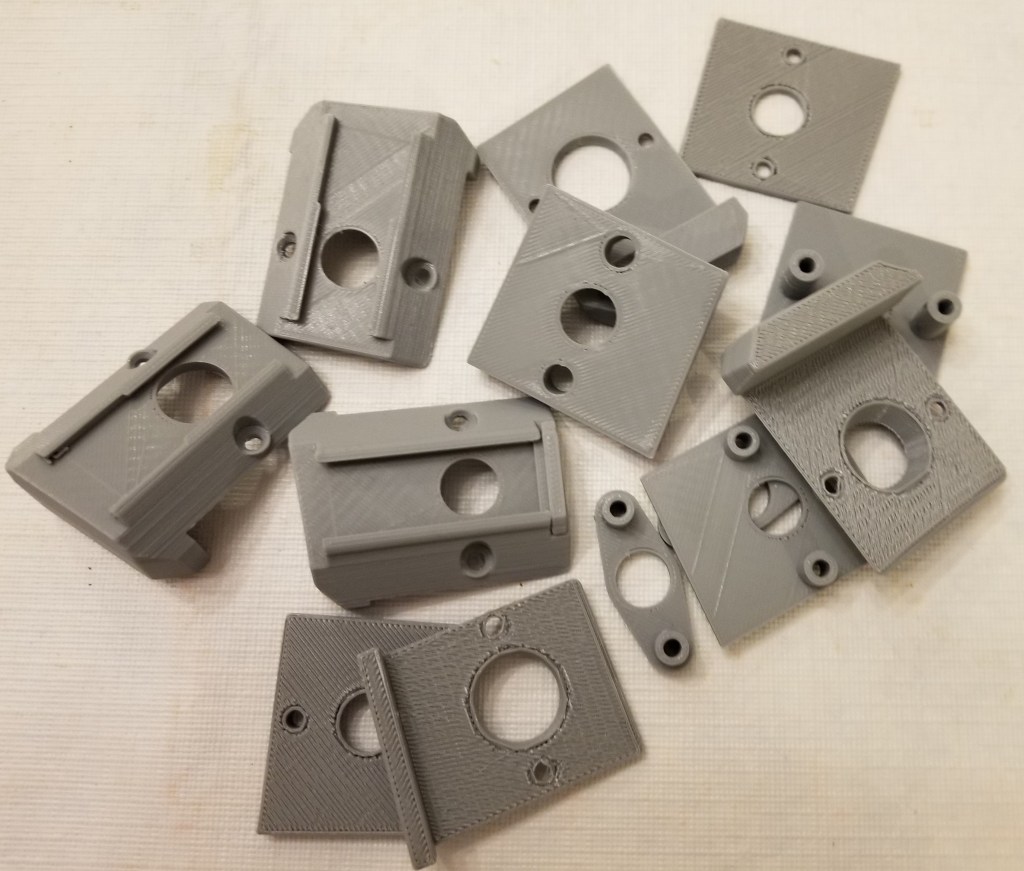
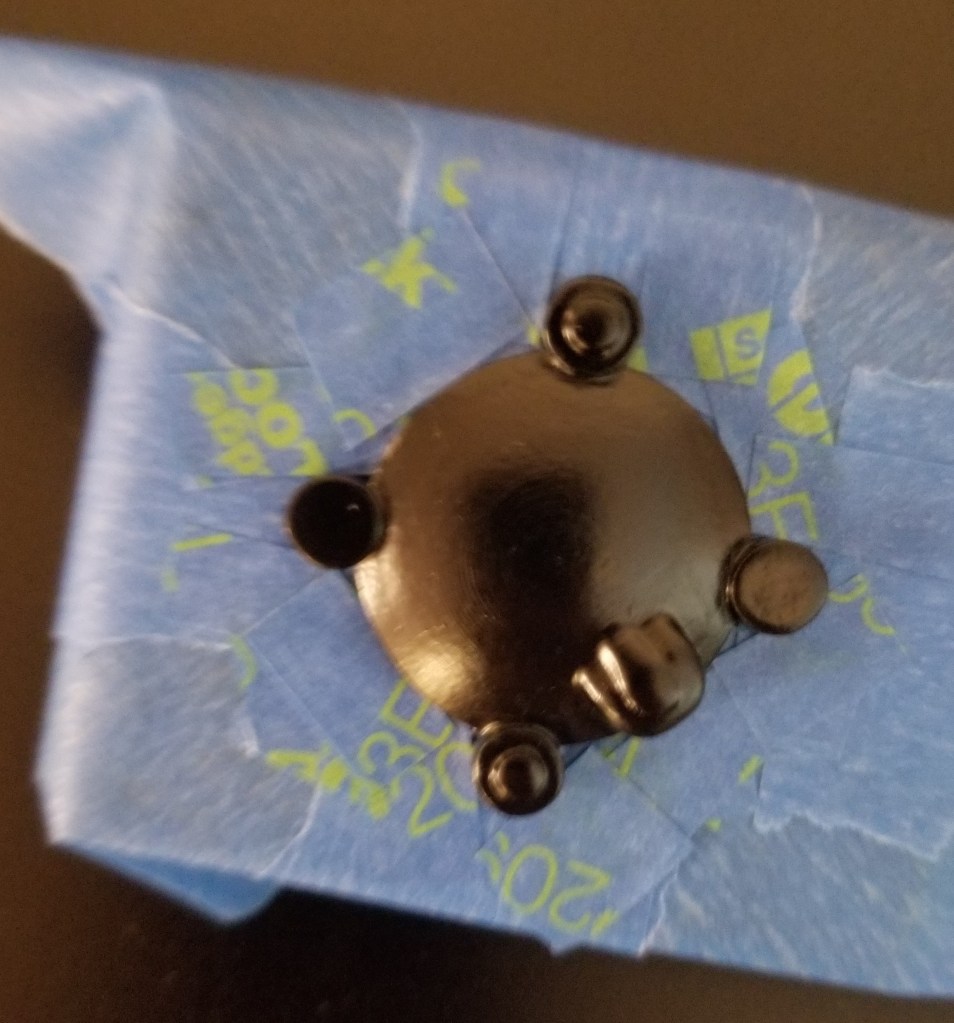
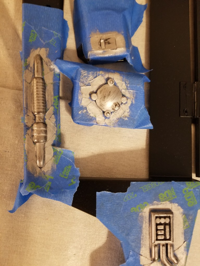
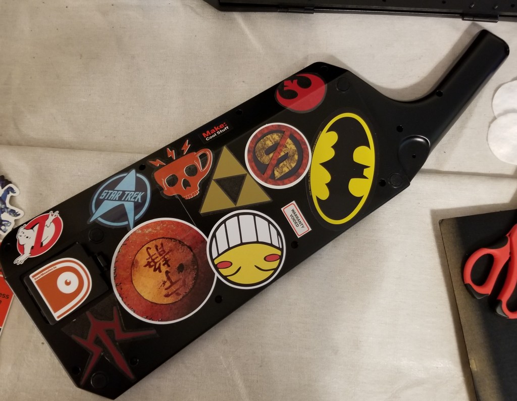
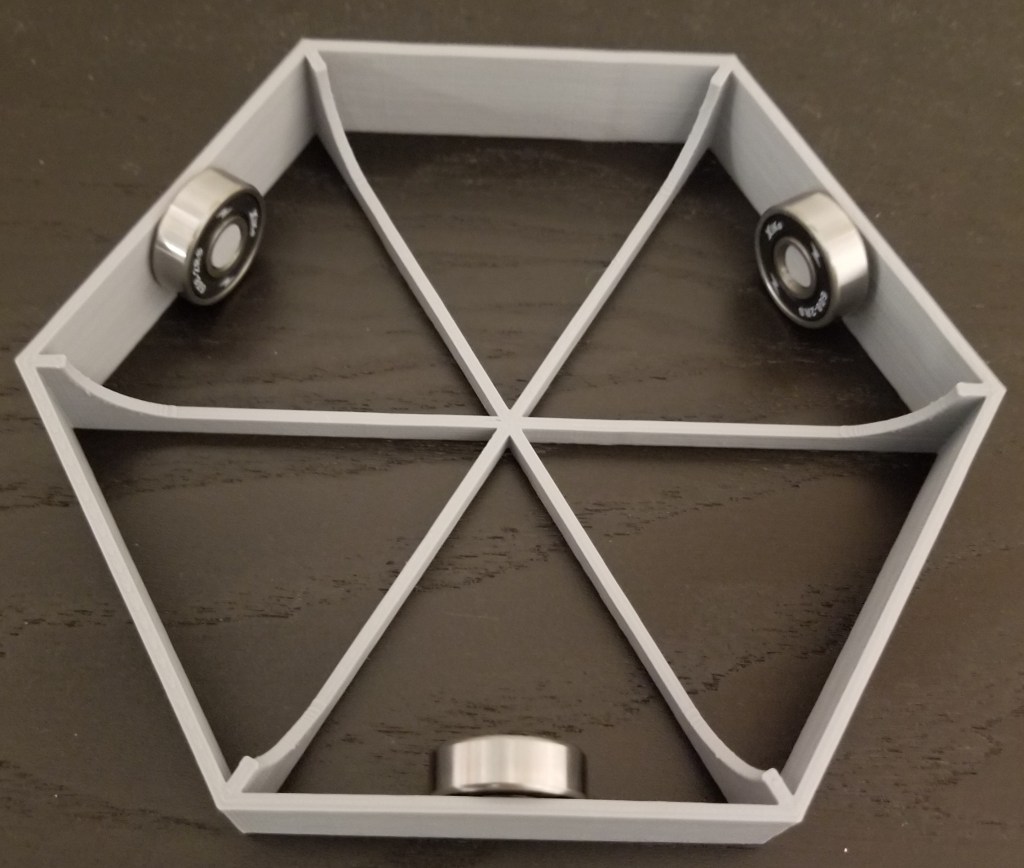
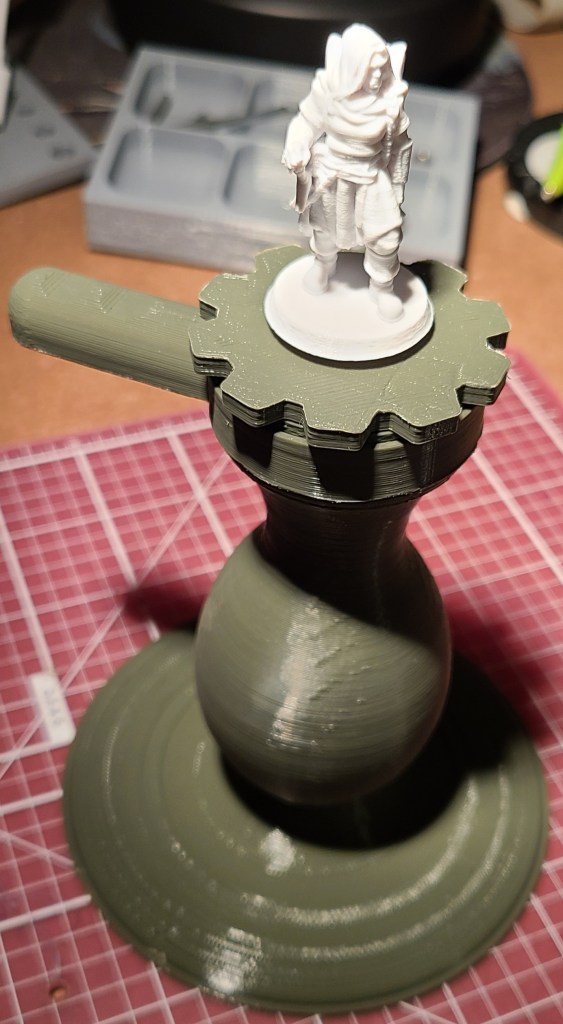
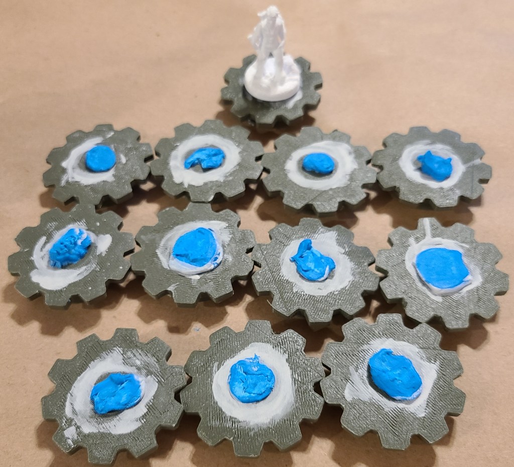
I had seen people use painting handles before, and they appeared to help a lot, so before I started painting I 3D printed one for myself, along with a lot of “pucks” to attach miniatures to in order to paint.

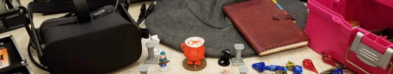
Here are some of the results of my early painting setup.

The miniatures from the kit.

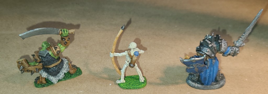
I love how the mail came out on the orc.

The first mini I ever printed.
Cyber dog from a kickstarter. All-metal creatures are easier to start out painting.

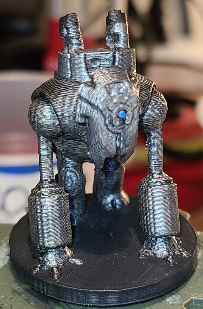
I’m pretty happy with these early results.

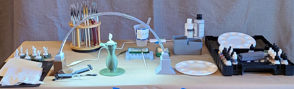
As I painted the miniatures, my painting setup has rapidly evolved.

It might be easier to cover various sections’ evolutions rather than try to keep track of them as setups. Here’s one of the earlier ones, and where it’s currently at.

Early Setup
Current Setup

Water

Originally I used a couple of red solo cups, one for clean water for use in mixing paints (with a dropper in it to measure when thinning washes), and one for rinse water. These were tall and easy to knock over. Not good.

I then switched to smaller plastic disposable cups, with labels on them so I didn’t get them mixed up. After watching some videos on painting and having some discussions with people who paint (a buddy of mine put me in touch with some other people who paint miniatures), I added a second rinse cup, because that appears to help clean brushes more thoroughly.

Finally (so far), I’ve switched the rinse cups to a couple of small plastic cups that aren’t as likely to tip, while still keeping one of the disposable plastic cups for clean water.

Paint Mixing and Cleanup

The painter’s kit recommended using kitchen parchment paper for mixing paints, but that got old fast. The parchment paper had to be cut into sections to be useable (yes I know that’s spelled weird, I don’t like standard spelling of “usable”), and it kept curling, making the paint run. I ordered some circular plastic paint palettes, and they work much better.

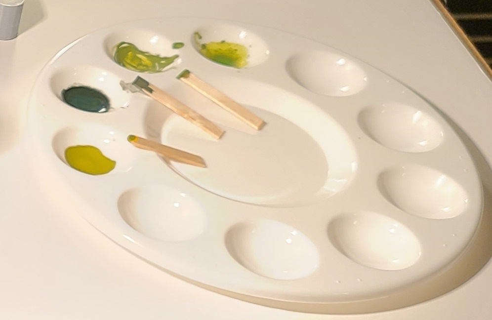
I use cut up wooden coffee stirrers to mix paints now. Originally I used some toothpicks I had. I should probably use plastic because of paint absorption, but so far it doesn’t appear to be a major wastage issue, since I’m not frequently running out of paint mixes before finishing what I’m painting. If I start painting a lot of minis in the same colors (if I were to start painting armies, for example) it might become an issue.

Cleaning the palettes was a bit of a challenge at first, but then I started keeping a container with a mixture of dish detergent and water nearby. As soon as I finish with a palette, it goes into the container. When I run out clean palettes, I use a stiff cleaning brush I keep in the container to scrub off any paint that managed to remain stuck to the palettes, then rinse and dry the palettes. It takes so much less time that way. At first I was trying to scrub with my fingers or a cloth and it did NOT go well.

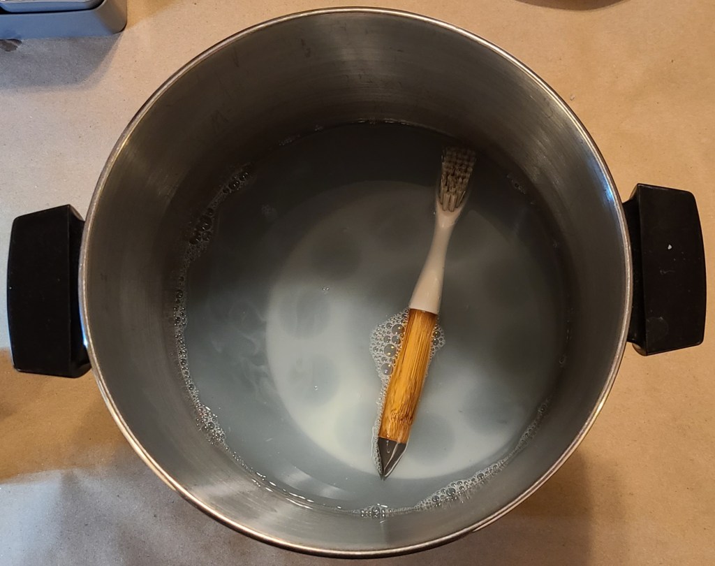
Eventually I want to get a smaller dedicated container for this with a lid, as that pot is my general crafting pot that I want to free up for anything else I might need it for.

Lighting

The glasses I mentioned earlier provides some additional lighting where I’m looking, and my usual workbench light originally provided the primary illumination, but it often required moving it around.

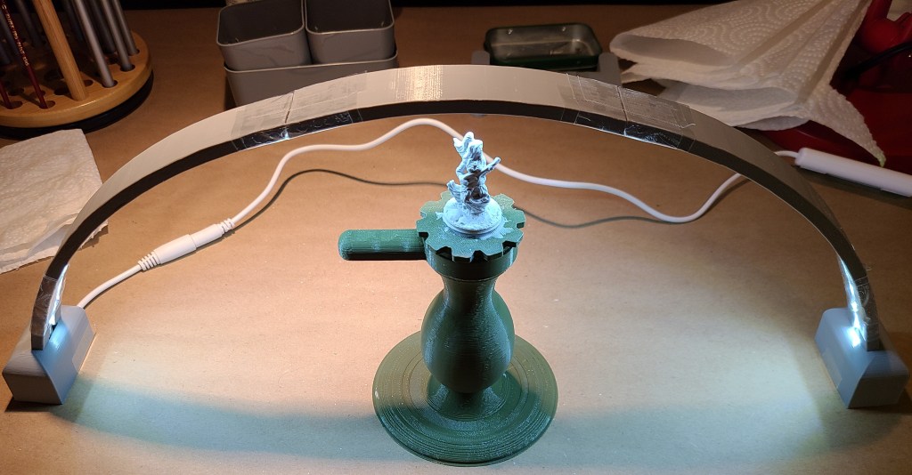
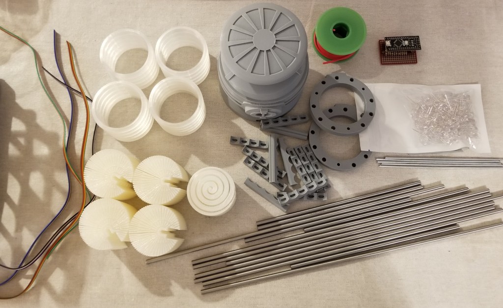
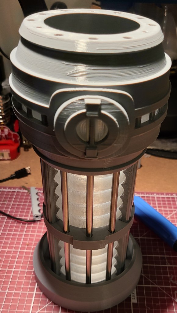
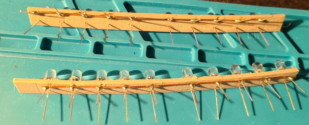
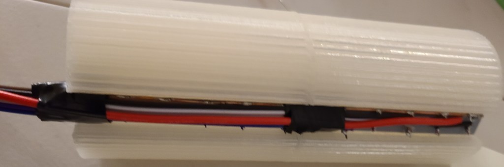
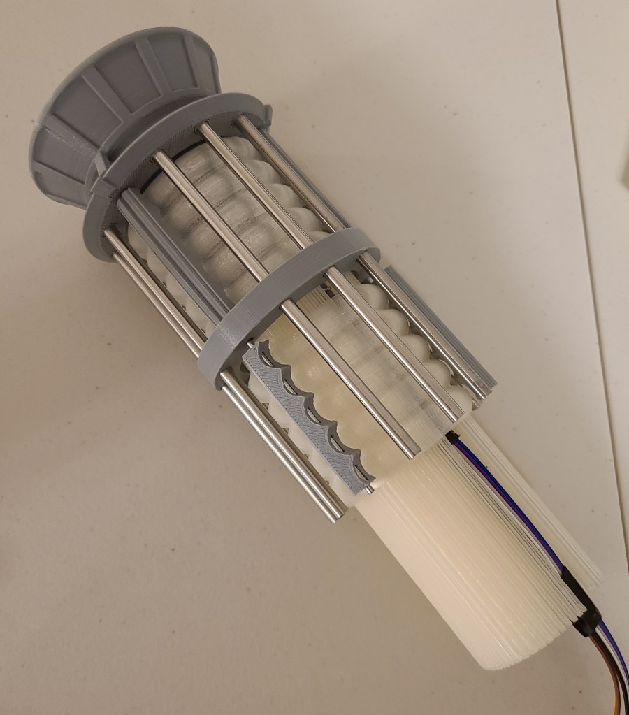
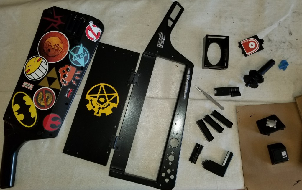
I decided to build something I had seen before on Thingiverse, an arch of LEDs providing light from various angles simultaneously, hopefully reducing the need to move a light around periodically while painting and photographing.

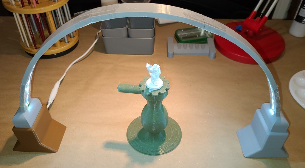
It seems to work decently for now, though I’ve only been using it for one day’s work at the time of writing. I covered the building shenanigans last week here:

Sanctum Upgrades: Arch Lamp

Location

I was originally painting on my primary workbench, covering up the area with a piece of foam core I cut to protect it, and moving stuff around. It allowed me to use the existing lighting at the work bench and mean I didn’t have to pull my auxiliary workbench out (it takes up living space).

This got annoying quickly, as with my 3D printed miniatures I have to clean them up before priming, so I had to keep switching the workspace back and forth. For now my painting setup is going to be a temporary or “deployable” setup that will occasionally live on my auxiliary workbench (aka the other folding table, yes, I like being pretentious sometimes). I still need to figure out storage for when I pack up my painting supplies, but that’s a problem for down the line.

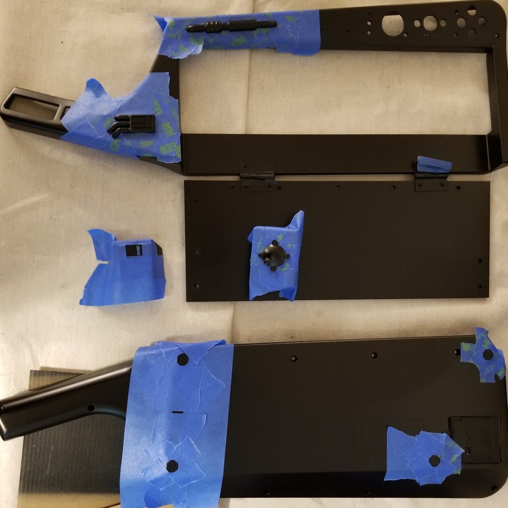
I covered the table in brown paper to protect it (like I generally do for projects, thanks Adam Savage) and have run my extension cable over to it for the lights. I just had to remember to run the wire a certain way so it’s not in the way of my rolling stool. Don’t want to fall off and injure myself because I forgot there was a wire there!

Paint Brushes and Holders

The kit came with a couple of starter brushes, and I was also gifted a nice set of fine tipped brushes. For the first 3 minis, I only used the brushes from the kit, as I wanted to learn more about brush care before putting any wear and tear on the nicer ones.

I also ordered a set of wider brushes for priming, which I’ve been using on all my 3D printed minis. I haven’t used the fine tipped brushes yet, but I’ve definitely been seeing places where they’ll be useful when I paint certain details.

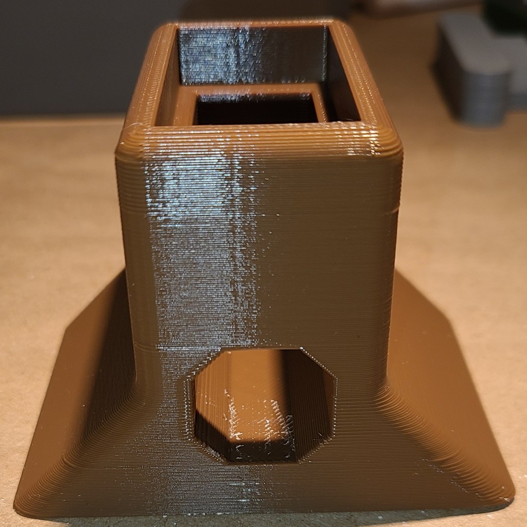
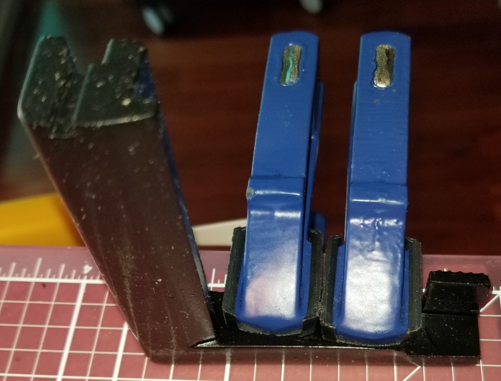
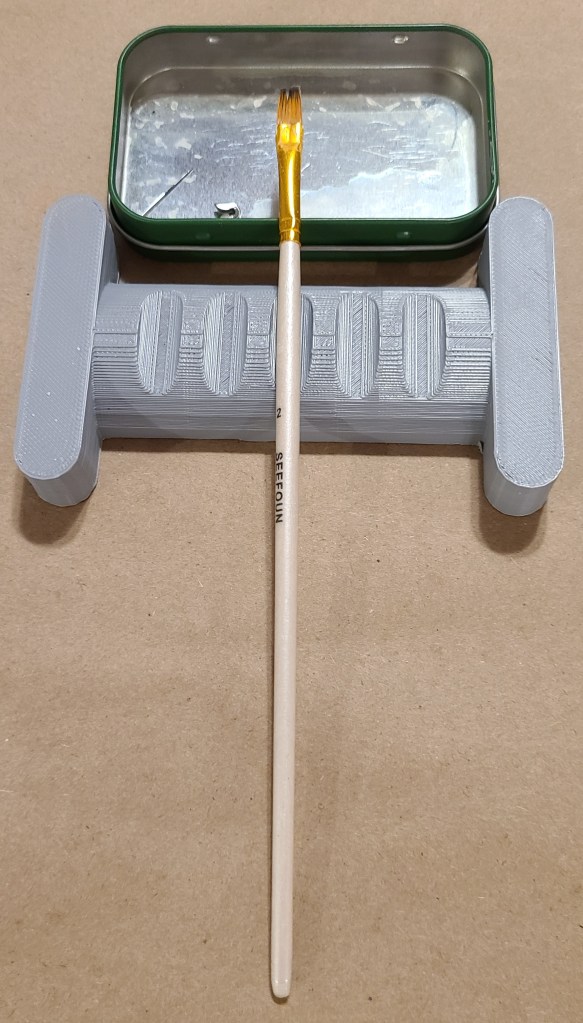
For holding the brushes when not actively in use, I initially just propped them against a small tin.

I 3D printed a brush holder that holds them over the tin very soon after, as the brushes kept rolling around.

I also wanted to see what additional brushes I had available. I couldn’t leave them just lying out on a flat surface as they could roll off or I could damage them by putting something on them, so I finally added a rotating brush stand.

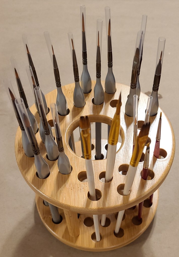
Now I can see an access what I have. I still want to go back and label it to keep it organized.

Paints and Primers

The minis in the kit did not require priming (Reaper Bones minis are like that), so I didn’t need any for that. The kit did include a number of paints to get started with, though.

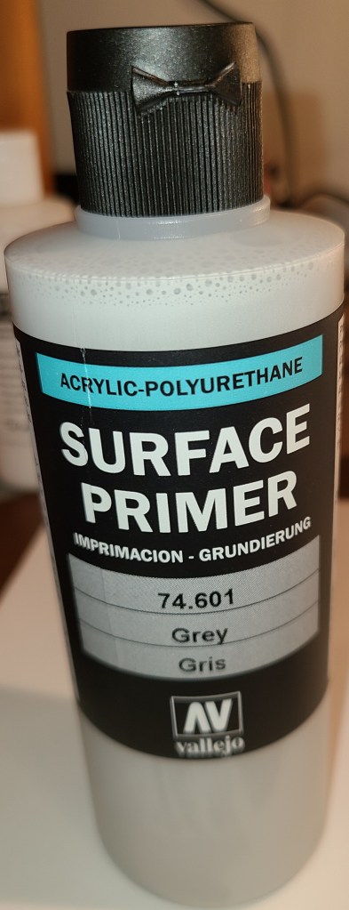
For the 3D printed ones I’ve been priming them, and I’ve got primers in two different colors. The white was for one thing that I still wanted to be white when I was done. I was hoping the gray would be darker so it’d be easier to distinguish from the white while I’m hand-priming (I’m kinda sick of spraying paints from my time with previous projects), but it’s still not that far off from white.

The starter kit covered a lot of colors, but it was missing some colors I’d want to use for my general collection (flesh tones and red, in particular… which sounds much more ominous than intended when I phrase it like that), so I did a bit of looking and decided to get the next kit in the series, which had the colors I was looking for, as well as more brushes, minis, and instructions. Now I think I have enough selection to paint the rest of my collection (after I get additional practice with the included minis).

That grid for holding the paints in place moves around and kept being a nuisance for regular use, so I locked it in place with hot glue.

Final Thoughts

I think this setup is settling towards a form now, but being this early in this new hobby I wouldn’t be surprised if there were further changes upcoming. At some point I want to replace the lamp with a better-made one, and I’ll probably swap out the wood coffee stirrers with plastic when these run out. Some people have recommended adding a wet palette to my setup, but I don’t yet see the need for one.

I’ve been enjoying priming and painting my miniatures, and look forward to gradually painting my 3D printed miniatures collection.

Sanctum Upgrades: Arch Lamp

I built this lamp as part of my rapidly upgrading painting setup, to provide light from different angles.

Originally I wanted to build a version of this lamp.

LED Bridge Lamp Universal Segment by Opossums on Thingiverse

However, it’s too big for my workspace, and it’s complex enough that I need to study it some before attempting scaling.

It’s a beautiful lamp, but doesn’t work for my original intent of painting on my primary workbench. It also would take a lot of space to store. I also wanted something I could construct quickly so I would have it available ASAP since I had paints coming in soon.

I did find this one, however:

LED Bridge Light Mini by FeedMePi

I ordered the LED strips and began printing.

Assembly, barring some issues I’ll get to further in this post, was rather straightforward. Cut the LED strips to length at one of the marked locations. Slide it through the guides section by section, coming in where you see the wire in the pictures below. Make sure that the LEDs are facing out of the slot. Then do the final attachment of the sections together.

When finished, set the arch upright, and turn the LEDs on. Then you’ll have lighting from many angles at once while working on your projects.

I did run into a couple issues while building this.

Issue 1: Warping

It’s become apparent that I have some warping issues with my 3D printer that is large enough to print these parts.

I ended up working around this by using a chisel to remove one of the pegs in each section, and using a lot of tape. It’s not perfect, but at least it gets it functional for now until I can reprint it properly.

Issue 2: Height

The arch is a bit short to comfortable use with the painting handle that I use for painting. While priming I don’t think that it’s so big of an issue, as I can easily just use the pucks to hold the mini, but for stability I’m going to want more space for both the stand and the brush in my hand.

To fix this, I designed and printed some extenders to raise the arch up approximately 2 inches. This gives me more space to work with.

They are designed to just stack the arch on top, and route the power cables out the back.

If you want to build one of these lamps with the extender pieces, you can find my extenders here:

Base Extender for LED Bridge Light Mini by Ralnarene

My current hope with this arch is that I will not have to use my workbench lamp on my secondary workbench, and can keep my painting and 3D printing workflows separate as much as possible. I also hope this means I’ll be able to see what I’m painting more clearly without having to move a lamp arm and my head around so much.

Light Staves: A Very Late Followup

This is a very late (approx 1 year) post, but oh well. I thought I should show you guys how the walking sticks I made last year turned out.

For those who are likely unfamiliar with what I’m talking about, here’s the original post:

Christmas Presents: Light Staves

I did in fact finish that project just before Christmas of last year, in time to hand out as presents.

When I last left off, I had designed the top portions of the staff, but had not figured out how to get the threads I wanted to connect it to the broom handle. I ended up remixing a model that someone else had made:

Broom and Paint Handle Threads 3/4″x5 by halley on Thingiverse.

I experimented with scaling a bit, and merged it with the interface part for the flashlight to create this connector:

Technomancer Adept Staff Broom Handle Connector

I used cutaway pieces like these to test the fit:

I just left the extra gap in there since it wasn’t really hurting anything. As a point of comparison, this is also how I test fit the other components.

Once I found out that everything fit, I had to paint the pieces. I used a primer/pigment spraypaint, with a couple coats of a clear gloss coat to minimize the occurrence of the paint rubbing off on things.

I simply clearcoated the “crystals” so light could still pass through.

Another modification I made was to the light of the flashlights themselves, by ordering some red filters sized for maglites, so that they wouldn’t interfere with people’s vision at night. Apparently the lenses are a bit vulnerable to heatwarping from the LEDs, but I didn’t think it was a significant enough issue to warrant leaving them out.

Since I knew these walking sticks would also be brought and stored indoors a lot, and I didn’t want to get parents angry at me for damaging their floors, I added little rubbery caps to the end of the walking sticks. Usually these are meant for chairs, but by boiling them and zip-tying them on, I think they were able to stay on well enough.

With that done, I had my semi-final products.

I say semi-final, because these were rather tall for the kids. I got some help from the rest of the family to figure out what height they needed to be, and then cut them down to their final heights for the kids.

I did find out quickly some modifications I may need to make for future versions. With all the lockdown times this year, I realized I still had leftover parts from making them, and started working on a variant for myself, incorporating what I had learned from the originals.

I still have work to do on it, but I think I like it. I need to reprint a couple parts with adjusted tolerances, then paint, glue, and assemble. I’m also thinking of making a connector to hang just this top portion from my belt if I feel like it, as a belt greeblie for cyberpunk costuming.

The tack at the bottom is holding a piece of metal in that positively retains the end cap of the maglite without just relying on the glue, which was a failing of the originals.

If at first you don’t succeed, iterate, iterate, iterate!

If anyone is interested in making their own (of the original design, I’m not sure if my personal one will be posted), the files are located here:

Technomancer Adept Staff Head

Technomancer Adept Staff Broom Handle Connector

Warp Core Table Lamp Finished!

This project is part of what first got me to get my first 3D printer, but I got discouraged at the time with print quality and later by my replacement printer being too small.

But I finally did it!

A while after I originally wanted to create it, someone updated the quality of the models and manufacturing methods, making it more feasible to do.

So, earlier this year, I posted about how I had printed the parts (though it took me a couple attempts).

Failed print…. this is where I found out Octoprint doesn’t like 12+ hr prints

3D printed parts, before I took the time to reprint the failed reaction chamber.

One of the nice things about this version is that most of the parts were broken into easier to print and clean up pieces. There was a bit of a tradeoff, though. It required coat hanger wire for some parts and replace others with stainless steel rods.

It was easy enough to buy the rods, and purchase and cut the steel coat hangers… but I was unable to cut the rods myself. I ended up supporting a local business and contacting my local machinist (who I’ve gone to before when there were metal parts I couldn’t fix or fab myself). It was kinda pricey… but precisely and cleanly cutting and finishing stainless steel is no joke, and this guy did an excellent job of it.

Unfortunately, I found out later that the lengths I have him did not precisely match what was needed for some of the 3D printed parts.

This led to a bit of experimentation with modifying the 3D models and reprinting the “tension members” to “cheat” them to a length that would work with the steel rods. That took a bit longer than it should have due to unexpected 3D printer problems.

Test fitting success!

By the way, if you’re wondering where the coat hanger wires went, they are inside those gray pieces around the clear section, spaced between the steel rods.

Getting the lights in there and getting them to work took a bit, but I finally finished that recently. The system runs off of an Arduino Nano board, with a small board to break the wiring out. Before I get to the final stuff, I want to share a lessons learned.

If you use a breadboard of any kind… check how the the holes are connected! For some reason I thought this board left the holes unconnected and that I’d have to spread solder between components to form connections. Turns out they were connected and it hadn’t occurred to me to look at the back of the board until after I had soldered the resistors on. This is also why it is a good idea to buy spares of parts (or multi-packs) when working on a project. Otherwise it could cost you a lot of time and extra shipping.

Great access for wires, right?
D’OH!

A new board and a lot of soldering later, this is what I ended up using:

Ignore the putty, they were holding the connector pins on for soldering

I realized that this time on a project I didn’t want to trap myself with my directly soldering disparate wires to the board, so I added connector pins so I could have removable cables for disassembly/modification. I wasn’t gonna bet on getting it right the first time!

To keep the count of LEDs and wires down a bit, I used the diffusers someone else had designed (links at the bottom).

The circular indentations are where the LEDs go.

It uses a “light pipe” design to spread the light around in a mostly circular pattern. There was even a special one for the reaction chamber…but I ended up not using that.

Wiring the LEDs took a while, but it was more tedious than it was difficult. I think it was mainly because I took the time to plan out what I was doing before I started in more detail, rather than trying to wing it and label a bunch of wires afterwards.

Paper, colored pencils, and a straight-edge go a long way towards helping planning. I used this to make a simplified guide for wiring… but I cleaned up after finishing and don’t know where it currently is.

To avoid going insane with trying to glue in each LED and try to solder all the connections with reasonable spacing, I designed and printed spacers that I could simply stick the wires of the LEDs through. I think the wires would have held, but to make things simpler on myself (and so they wouldn’t push out during soldering) I hot glued them after putting them in.

Madness? THIS. IS. PLANNING!


To drastically cut down on the number of wires required, I soldered all of the negative terminals to a common grounding bus bar made from a bare copper wire.

10 wires enter, one wire leaves.

Referencing the drawings I had made earlier, I soldered some ribbon cable to the positive terminals, allowing me to have traceability through color-coding. The wiring is mirrored on the opposite side, so that each control output from the electronics board controls the lights in the mirrored position on top and bottom of the warp core lamp. This keeps the number of control pins needed down, and simplifies the coding.

Wire the rainbow… to save yourself headaches later.

These lights on the spacer bars fit snugly into the diffusers.

The top section. Easily identifiable by the big red grounding wire because I forgot to connect the grounding wire first. Also…snip your extra wire leg length to reduce problems.

As mentioned in the note above, I forgot to wire the ground wire first on the top section, meaning I had to add it in last, connecting it at the far end rather than the close end. In the bottom section I did it first, because I really needed room for the power/programming USB cable to fit in.

These segments then slid into the corrugated sections.

This was actually when I realized the grounding wire blunder. All positive and no negative wires.

An intermediate stage for no reason other than I like this picture.

Here’s how the wires connected up before the final closing of the casing.

Note the removable connectors for all the wires in case I needed to adjust anything. The colorcoding made connecting them to the board a breeze. The USB cable goes out the bottom for programming and power.

Now we get to where I kinda got angry. Here are the parts just before I was planning to connect the last couple wires and close it up.

Before I realized my planning failure.

Look at the circuitry. Look at the diffuser that’s supposed to go into the central reaction chamber. Now look at the reaction chamber. Do you see it yet?

THE DIFFUSER AND THE CIRCUIT DON’T BOTH FIT INTO THE CHAMBER AT THE SAME TIME.

I had planned for this somewhat with the board, but hadn’t fully taken into account the flexibility of the wires or the added height of the removable connectors.

Thankfully,

1) the diffuser isn’t 100% necessary (though the light would look better in that section

2) the diffuser was weak

3) RAL CAN CRUSH DIFFUSER WITH BARE HANDS AND EXTRACT LEDS INTACT

I kinda went barbarian on it in my desire to finish. I ripped the central diffuser apart, and just shove the LEDs in the compartment with the rest. Also, after a test fitting and plugging it in, I realized that the arduino had red LEDs that clashed with the color scheme, and put some electrical tape over them to get rid of the distracting red glow.

I closed the thing up… and then got to do something that still makes me chuckle a bit.

DRAMATIZATION OF ACTUAL EVENTS

I pulled out the rubber mallet and began gently tapping on the end of the warp core to make sure all the rods were seated as well as they could be.

After a bit of updating some code I wrote for this years ago (and cursing at two different computers for a few hours because they didn’t want to behave with uploading to the arduino) I finally got it turned on.

Engineering to bridge, the reactor is online!

I went through a few iterations of code and pseudocode (and had to remind myself that with this board the counting started at 2 rather than 0 or 1), and finally got it to a state I liked.

Here’s the initial light pattern I went with:

I’ve got an intermediate version of this one somewhere with an extra delay built in after the FOR loop because I didn’t like that the light jumped immediately from the bottom LED to the top again. It just seemed jarring.

Here’s what I’ve most recently decided to use:

This one has 2 or 3 “waves” at a time passing through each end to the center. It looks less like a jarringly looped GIF than some of the other iterations I went through.

I originally planned on plugging this into the raspberry pi that I control my 3D printers with, but apparently Octoprint gets confused by the extra USB connection, so I have it connected to a USB wall adapter for the moment. Though I have realized I can plug it into the USB adapter in my car as well…

I hope you all enjoyed this, and I’m glad to have finally finished this project after years of wanting to build this, and I was finally able to take this off my project board.

Reference Links For Construction:

Here’s the original I saw that inspired me years ago:

Warp Core Table Lamp by ThePlanetMike

Here’s the one I actually made:

1701-D Warp Core (HI-RESOLUTION) by Novel_Mutations

Here’s the LED Diffuser I used to reduce the number of LEDs needed in the build:

LED Diffuser for High Resolution 1701-D Warpcore by Novel_Mutations

My github page for the light sequence on the arduino:

Warp-Core-Lamp-Arduino-Nano

πoneer Falchion

Now that I’ve submitted it as my entry for the 2020 Zero Day competition, I feel like I can share what I’ve been working on lately.

This may end up being the first in a series of “Standard Runner’s Constructs,” and the instructions are written as such, in an in-universe style. The idea is that runners are trying to make sure their future teammates are properly equipped and educated. If you “can’t find good help anymore,” sometimes you’ve gotta train your own.

I present the 𝝅oneer Falchion, a pi zero w based micro cyberdeck (or microdeck).

Runner’s First Cyberblade, or a “Decker’s Sidearm”

The backside. Note the data-quillions, recessed power switch, and hinge.
Operating configuration.
Easy charging port.

I took inspiration in designing this from the Austro-Hungarian M1853 Pioneer’s Falchion. I had gotten the first inkling of an idea of a blade shape from the shape of the keyboard, and then went poking and asking around to find a blade with a somewhat similar shape. That’s what informed the shape of the hilt and the placement of the quillions in particular.

The features include a micro-USB charging port on the hilt end, two USB-A “data-quillions”, a touchscreen display, and a wireless keyboard that folds on a hinge along the back of the “blade” into the operating position under the display. The power switch is accessible through a hole on the backside of the device.

I designed and built it for the competition hosted here:

https://www.cyberdeck.cafe/post/deck-builders-competition

The gist of it is that we are holding a mini virtual maker faire, with a competition portion. The competition requires using a Raspberry Pi Zero (or Zero W for the wireless version) as the core of a cyberdeck that we designed in a limited amount of time, with a limited number and volume of 3D printed components, and including the required models and instructions as our entry.

The winner gets their design printed in resin and shipped to them.

As part of the competition I had to submit the 3D models and instructions, but I also have them hosted here:

https://www.thingiverse.com/thing:4601417

https://github.com/Ralnarene/SRC000_Zero_Stack

https://github.com/Ralnarene/SRC001_Pioneer_Falchion

Feel free to make your own. I’d love to see photos!

“Medieval” Backpack Upgrade Finished

This past week I finished my updates to the backpack. I cleaned up the leather straps, replaced the corroded fittings, cut the straps to length, punched new holes, and attached the straps to the frame. Here are the results.

The replacement buckles look better than the originally planned buckles! I doubt you’d notice, but I had to remove and adjust that felt padding on the lower frame by narrowing the area covered by it. Otherwise the leather straps would have to wrap around the padding, which doesn’t provide as secure of a hold.

From this top view you can see the leather badges on the bag that I keep on top of the overall pack. I found the bag and those badges at DragonCon a few years back. The in-character explanation is that I’d carry the whole thing as I walked from town to town, and set it down in my room at an inn, taking my lighter bag around shopping in town.

At some point I still need to go through what I carry in and on the pack for events. Right now I’ve got it in a kind of “all-purpose” configuration, with a bota bag for water, a small bag for local shopping, and a wool blanket for warmth/shelter. I’d like to figure out 1) what I would want to carry if I decided to take this camping and 2) what I would want to carry if I were actually the character that this was designed for. What tools would I carry for my trade? What in-period essentials would I carry for survival? Would I have anything in there to deal with bandits or wild animals?

As someone pointed out to me recently, I apparently like to have a story behind the things I create.

Keytar Power Switch

I got fed up with the power cables sticking out of the side of the case, so I decided to make the power switch a more integral part of the build. Also, I didn’t like the gaping hole in the case.

There were two power switches, one for the deck itself, and one for powering the USB hub. I modified this one for the hub, deciding to route it fully inside the case, even though that means I have to briefly open the tray to turn on the hub.

I also made this cable up for the main power to the Pi.

As part of this design process there was a lot of tinkering and iterating.

And, I mean a LOT of tinkering. This is what I ended up with:

This image has an empty alt attribute; its file name is 20200516_103531.jpg

I knew I liked the idea of a red safety cover for the switch, but those are designed to turn a regular flip switch off when they closed. I needed a way to have a cover a switch while the thing was still powered on. I found the switch that would fit through the hole of the safety cover (after a little… modification with the deburring tool), and figured out how to design the little bugger to hole the actual switch, the switch cover, allow for proper free movement of the switch to function, and attach the switch neatly and securely to the case. I’ll spare you the iterations, but it took a while, and I think I got it to look pretty good and hold well. I like that I have a red power button under a red safety cover now. It just feels… right.

Warp Core Table Lamp

I’ve been wanting to build one of these for years, since before I got my first 3D printer, but I had so many problems with my 3D printers on long prints that I never got around to it.

Well, I’m fixing that now!

For one thing, the models for this have been redone drastically, increasing quality and reducing the print time.

Here’s the original: Warp Core Table Lamp

And here’s a redone version: 1701-D Warp Core (HI-RESOLUTION)

It’s also been downsized slightly, which makes the large parts fit on my smaller 3D printer.

For another, I’ve been fixing my 3D printers, and have had all this monitored print time available recently, so I’ve had no excuse NOT to make it anymore. So, I’ve been spitting out the parts for this thing lately.

Those translucent sections were much larger and more complex in the original model, each made of 5 toroids. Also, many pieces were replaced with metal rods that I was able to order on Amazon, I just have to cut them down to the correct length.

So… yet another project ongoing! I’ve gotten the tools and hopefully all the parts I need, so when I have some more time (I’ve been kinda busy) I’ll be:

  1. Writing the arduino code for controlling it
  2. Testing the code on a breadboard
  3. Soldering an absurd number of connections
  4. Cutting a bunch of metal rods with a reciprocating saw
  5. Filing some metal bits to safer edges
  6. Assembling the lamp

Keytar Accents and Details

After finishing the keytar’s primer/color coat, I started prepping to do the details. As mentioned in a previous post, I was using Rub’n’Buff to give a bit of a metallic finish to the details.

Like with any good detail work (unless perhaps you have a LOT more skill and confidence than I do), I prepped the sections I was going to accent by taping around the parts I wanted to add color too. This helps keep the transition between colors sharper and cleaner. It used a lot of painter’s tape and prep time, but it was worth it. I also taped around the feet on the backside of the case to protect the areas around them when sanding. I… kinda forgot to tape over them before painting, and I needed to remove the paint so that the rubber feet would work properly.

It can take a while to tape around these to my satisfaction, as I’m trying to preserve a lot of detail in the process and not look sloppy. It took a lot of small bits of tape, and some work with an exacto blade. As an example of what I’m talking about, here’s how I had taped up the universal greeblie for painting. I had to be careful to tape around all those curves.

Once I finished taping the pieces up, and through a bit of trial and error, I was able to add something of a metallic finish that I had wanted. Here it is, before and after removing the tape (there may have been an extra application of Rub’N’Buff between photos). Note the amount of extra finish that was on the protective tape that didn’t end up on the surrounding black paint.

Finished with the accents, I started decorating with stickers. I had a bit of trouble with some of them, and I’m not entirely happy with the results but, eh, you live and learn. I know a bit more of what to expect the next time I do something similar. The vinyl sticker with my logo was the hardest one to put in.

The others took a bit of planning for placement, but weren’t so bad to apply, as each sticker was a single solid piece.

After applying all that, I had to apply some more paint. A few coats of glossy clear enamel to protect everything and seal it in, and a coat of matte clear paint to knock the gloss off. The results were alright, but I think if I were to redo this I would use a painted on clear lacquer, for a thicker, stronger coat. Some of the stickers don’t adhere as well as they should, and the spray painted clear coat doesn’t force it down like a lacquer might. I also noticed that with some hard objects it was easy to accidentally add marks to the surface of the paint, it’s something about the clear coats, but at this point I don’t want to worry with attempting a fix, and I’ll just call it “built-in weathering.”

Oh, before I forget, one of my lessons learned I would like to share.

DO NOT LET YOUR SPRAYPAINTED PLA PLASTIC PARTS DRY IN THE SUN. I started getting warping in one of my parts because I didn’t realize it was in direct sunlight, and I had to try an emergency repair with clamping while it was still flexible.

Here’s all the parts after stickering and painting. Oh, and I was painting a door opening tool at the same time as well.

It was around this point that I decided that I wanted to make sure I finished the USB hub add-on and a more integrated power switch before reassembling it, but that’s a topic for another post.

Let me know if you have any questions about the processes in these posts. I’m trying to write these over a month after the fact, and have been limiting some of the details in order to progress forward.

Sanctum Upgrades: Rotating Miniatures Display

I decided that I wanted to be able to display and easily access my collection of D&D miniatures. I came across a concept for reusing empty filament spools. Their version had faceplates, but for the moment I just want to at least get this thing functional. I stacked my empty spools, and connected them with some tacky material.

It’s convenient, showing off my minis for ease of access… but the back half is hard to see and reach. This is where the turntable comes in. I had tried one version where it was a plate sitting on a single skateboard bearing, but that was too brittle and the whole thing wobbled (the spools make it top-heavy). So, I switched to this design:

You can find the original turntable design on Thingiverse here:

Manual Turntable by printedprops

I didn’t need the top plate, seeing as the bottom spool provides a surface to rotate on, but the bottom plate does provide a much more stable base to rotate the entire tower on.

I may end up upgrading the tower to have the nice stonework facings here, but so far I don’t want to give up the printer runtime for it. It was the inspiration for this project, though.

At any rate, I now have a way of seeing what minis I have, instead of having to dig through plastic containers. Maybe post-quarantine I can use it for hosting some RPGs.