
This project is part of what first got me to get my first 3D printer, but I got discouraged at the time with print quality and later by my replacement printer being too small.
But I finally did it!
A while after I originally wanted to create it, someone updated the quality of the models and manufacturing methods, making it more feasible to do.
So, earlier this year, I posted about how I had printed the parts (though it took me a couple attempts).
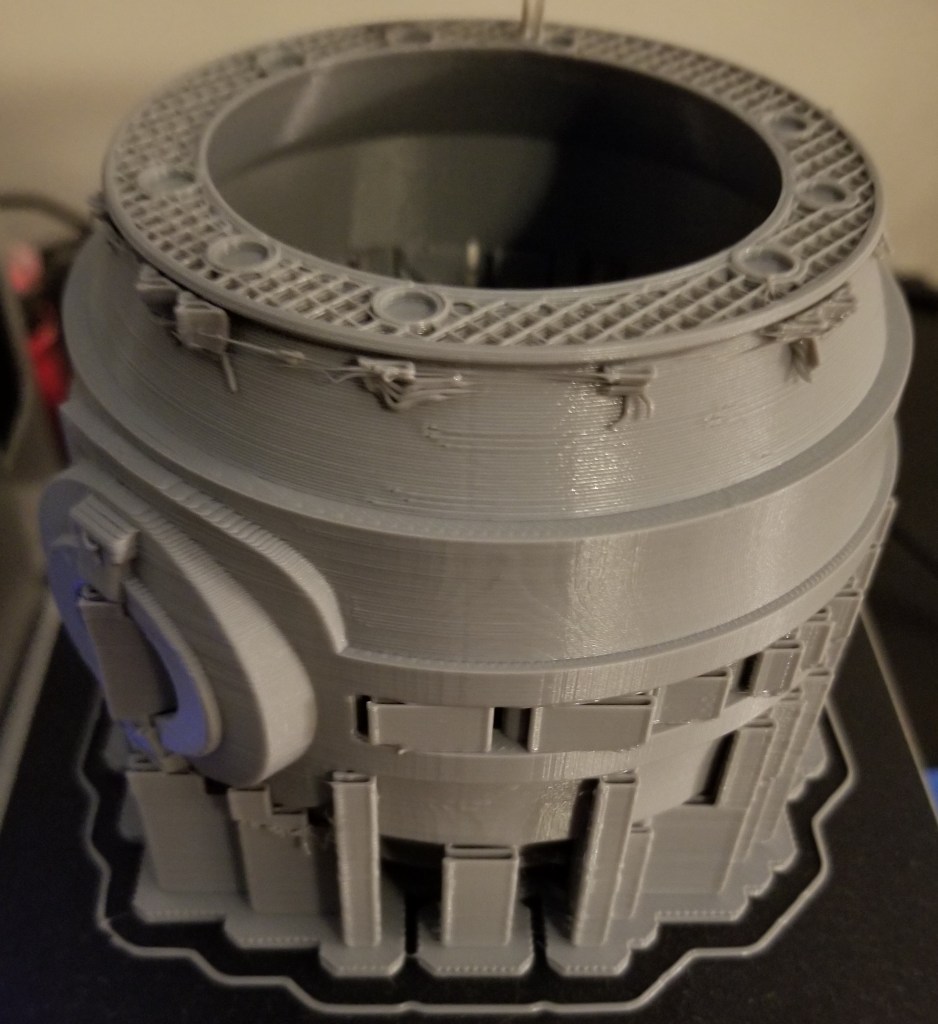
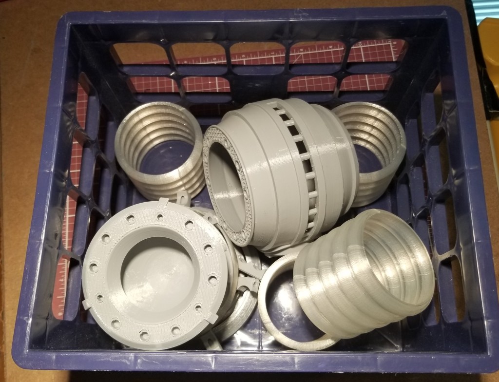
One of the nice things about this version is that most of the parts were broken into easier to print and clean up pieces. There was a bit of a tradeoff, though. It required coat hanger wire for some parts and replace others with stainless steel rods.
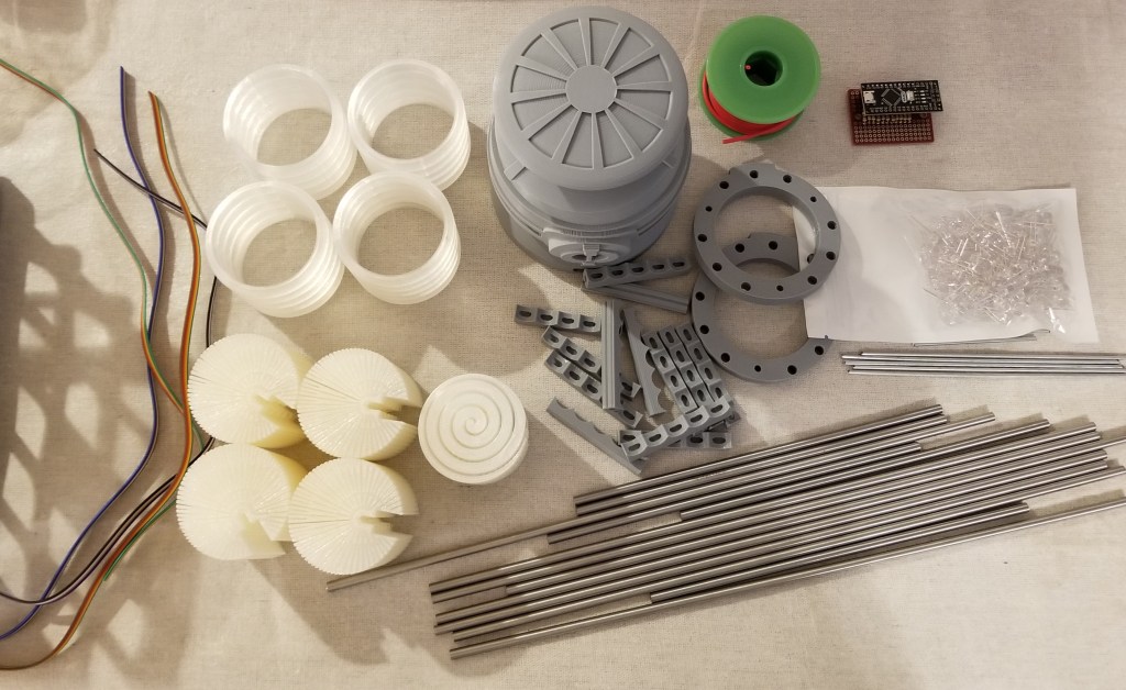
It was easy enough to buy the rods, and purchase and cut the steel coat hangers… but I was unable to cut the rods myself. I ended up supporting a local business and contacting my local machinist (who I’ve gone to before when there were metal parts I couldn’t fix or fab myself). It was kinda pricey… but precisely and cleanly cutting and finishing stainless steel is no joke, and this guy did an excellent job of it.
Unfortunately, I found out later that the lengths I have him did not precisely match what was needed for some of the 3D printed parts.
This led to a bit of experimentation with modifying the 3D models and reprinting the “tension members” to “cheat” them to a length that would work with the steel rods. That took a bit longer than it should have due to unexpected 3D printer problems.
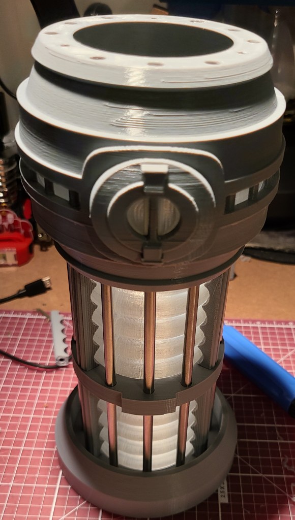
By the way, if you’re wondering where the coat hanger wires went, they are inside those gray pieces around the clear section, spaced between the steel rods.
Getting the lights in there and getting them to work took a bit, but I finally finished that recently. The system runs off of an Arduino Nano board, with a small board to break the wiring out. Before I get to the final stuff, I want to share a lessons learned.
If you use a breadboard of any kind… check how the the holes are connected! For some reason I thought this board left the holes unconnected and that I’d have to spread solder between components to form connections. Turns out they were connected and it hadn’t occurred to me to look at the back of the board until after I had soldered the resistors on. This is also why it is a good idea to buy spares of parts (or multi-packs) when working on a project. Otherwise it could cost you a lot of time and extra shipping.


A new board and a lot of soldering later, this is what I ended up using:

I realized that this time on a project I didn’t want to trap myself with my directly soldering disparate wires to the board, so I added connector pins so I could have removable cables for disassembly/modification. I wasn’t gonna bet on getting it right the first time!
To keep the count of LEDs and wires down a bit, I used the diffusers someone else had designed (links at the bottom).

It uses a “light pipe” design to spread the light around in a mostly circular pattern. There was even a special one for the reaction chamber…but I ended up not using that.
Wiring the LEDs took a while, but it was more tedious than it was difficult. I think it was mainly because I took the time to plan out what I was doing before I started in more detail, rather than trying to wing it and label a bunch of wires afterwards.

To avoid going insane with trying to glue in each LED and try to solder all the connections with reasonable spacing, I designed and printed spacers that I could simply stick the wires of the LEDs through. I think the wires would have held, but to make things simpler on myself (and so they wouldn’t push out during soldering) I hot glued them after putting them in.
To drastically cut down on the number of wires required, I soldered all of the negative terminals to a common grounding bus bar made from a bare copper wire.
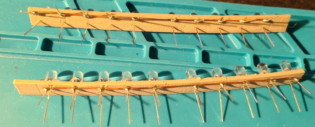
Referencing the drawings I had made earlier, I soldered some ribbon cable to the positive terminals, allowing me to have traceability through color-coding. The wiring is mirrored on the opposite side, so that each control output from the electronics board controls the lights in the mirrored position on top and bottom of the warp core lamp. This keeps the number of control pins needed down, and simplifies the coding.

These lights on the spacer bars fit snugly into the diffusers.
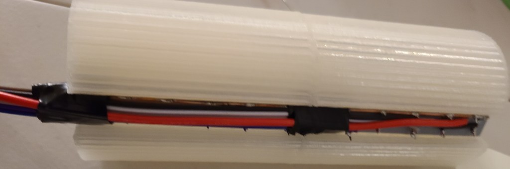
As mentioned in the note above, I forgot to wire the ground wire first on the top section, meaning I had to add it in last, connecting it at the far end rather than the close end. In the bottom section I did it first, because I really needed room for the power/programming USB cable to fit in.
These segments then slid into the corrugated sections.

Here’s how the wires connected up before the final closing of the casing.

Note the removable connectors for all the wires in case I needed to adjust anything. The colorcoding made connecting them to the board a breeze. The USB cable goes out the bottom for programming and power.
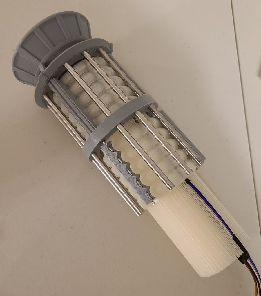
Now we get to where I kinda got angry. Here are the parts just before I was planning to connect the last couple wires and close it up.

Look at the circuitry. Look at the diffuser that’s supposed to go into the central reaction chamber. Now look at the reaction chamber. Do you see it yet?
THE DIFFUSER AND THE CIRCUIT DON’T BOTH FIT INTO THE CHAMBER AT THE SAME TIME.
I had planned for this somewhat with the board, but hadn’t fully taken into account the flexibility of the wires or the added height of the removable connectors.
Thankfully,
1) the diffuser isn’t 100% necessary (though the light would look better in that section
2) the diffuser was weak
3) RAL CAN CRUSH DIFFUSER WITH BARE HANDS AND EXTRACT LEDS INTACT
I kinda went barbarian on it in my desire to finish. I ripped the central diffuser apart, and just shove the LEDs in the compartment with the rest. Also, after a test fitting and plugging it in, I realized that the arduino had red LEDs that clashed with the color scheme, and put some electrical tape over them to get rid of the distracting red glow.
I closed the thing up… and then got to do something that still makes me chuckle a bit.

I pulled out the rubber mallet and began gently tapping on the end of the warp core to make sure all the rods were seated as well as they could be.
After a bit of updating some code I wrote for this years ago (and cursing at two different computers for a few hours because they didn’t want to behave with uploading to the arduino) I finally got it turned on.

I went through a few iterations of code and pseudocode (and had to remind myself that with this board the counting started at 2 rather than 0 or 1), and finally got it to a state I liked.
Here’s the initial light pattern I went with:
I’ve got an intermediate version of this one somewhere with an extra delay built in after the FOR loop because I didn’t like that the light jumped immediately from the bottom LED to the top again. It just seemed jarring.
Here’s what I’ve most recently decided to use:
This one has 2 or 3 “waves” at a time passing through each end to the center. It looks less like a jarringly looped GIF than some of the other iterations I went through.
I originally planned on plugging this into the raspberry pi that I control my 3D printers with, but apparently Octoprint gets confused by the extra USB connection, so I have it connected to a USB wall adapter for the moment. Though I have realized I can plug it into the USB adapter in my car as well…
I hope you all enjoyed this, and I’m glad to have finally finished this project after years of wanting to build this, and I was finally able to take this off my project board.
Reference Links For Construction:
Here’s the original I saw that inspired me years ago:
Warp Core Table Lamp by ThePlanetMike
Here’s the one I actually made:
1701-D Warp Core (HI-RESOLUTION) by Novel_Mutations
Here’s the LED Diffuser I used to reduce the number of LEDs needed in the build:
LED Diffuser for High Resolution 1701-D Warpcore by Novel_Mutations
My github page for the light sequence on the arduino:
