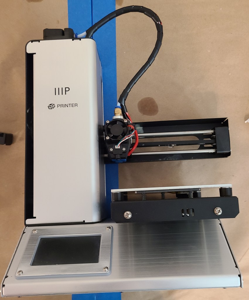
I’ve long complained that one of my printers, the Monoprice Select Mini Pro, was not designed well for maintenance. The vertical column does not seem particularly accessible. The column is made of a couple pieces of bent sheet metal that is structural but can’t be removed without fully disassembling it, and I had no idea how to do that and be able to put it together again.
I was in the process of photographing it to point out to someone where there should be a door on the design so you can access the Z-axis screws and rods for lubrication. And I noticed something.
Wait a minute…
That silvery piece is not one continuous piece of metal!
In fact, it’s cut in places where I would want to be able to remove a panel!
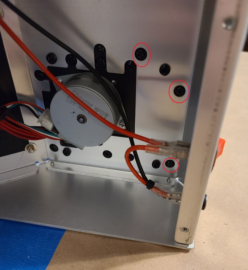
I had to open up the bottom and carefully look for what appeared to be the appropriate screws.
Screws circled in red.
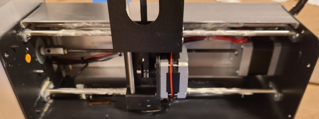
The screws on the top of the column were pretty obvious. Once I removed it, my hunch bore out. It actually was an access panel. I’d been trying to lubricate it the hard way.
I cleaned up the overspray from previous maintenance cycles, and directly applied lubricant to the rods and rails this time.
Sometimes we really should take more time to get thoroughly acquainted with the inner workings of our tech!
At least now I know how to get at parts. That had been driving me nuts ever since I’ve had one of these.
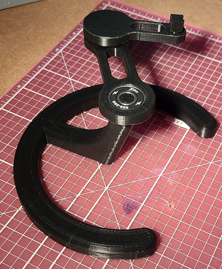
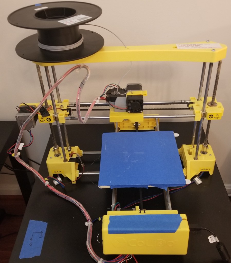
I’ve been on a spree upgrading my workspace/living space. With a new workstation and working arrangement, I started getting annoyed with the mouse cable moving around and making extra noise.
I had the printer time available and a couple of skateboard bearings already on hand. I decided to go with black filament to keep the aesthetic matching with other hardware around my computer and let it blend into the background a bit.
I did in fact finish that project just before Christmas of last year, in time to hand out as presents.
When I last left off, I had designed the top portions of the staff, but had not figured out how to get the threads I wanted to connect it to the broom handle. I ended up remixing a model that someone else had made:
I just left the extra gap in there since it wasn’t really hurting anything. As a point of comparison, this is also how I test fit the other components.
Once I found out that everything fit, I had to paint the pieces. I used a primer/pigment spraypaint, with a couple coats of a clear gloss coat to minimize the occurrence of the paint rubbing off on things.
I simply clearcoated the “crystals” so light could still pass through.
Another modification I made was to the light of the flashlights themselves, by ordering some red filters sized for maglites, so that they wouldn’t interfere with people’s vision at night. Apparently the lenses are a bit vulnerable to heatwarping from the LEDs, but I didn’t think it was a significant enough issue to warrant leaving them out.
Since I knew these walking sticks would also be brought and stored indoors a lot, and I didn’t want to get parents angry at me for damaging their floors, I added little rubbery caps to the end of the walking sticks. Usually these are meant for chairs, but by boiling them and zip-tying them on, I think they were able to stay on well enough.
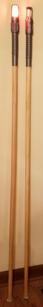
With that done, I had my semi-final products.
I say semi-final, because these were rather tall for the kids. I got some help from the rest of the family to figure out what height they needed to be, and then cut them down to their final heights for the kids.
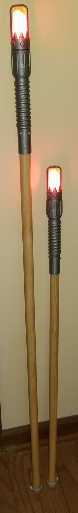
I did find out quickly some modifications I may need to make for future versions. With all the lockdown times this year, I realized I still had leftover parts from making them, and started working on a variant for myself, incorporating what I had learned from the originals.
I still have work to do on it, but I think I like it. I need to reprint a couple parts with adjusted tolerances, then paint, glue, and assemble. I’m also thinking of making a connector to hang just this top portion from my belt if I feel like it, as a belt greeblie for cyberpunk costuming.
The tack at the bottom is holding a piece of metal in that positively retains the end cap of the maglite without just relying on the glue, which was a failing of the originals.
If at first you don’t succeed, iterate, iterate, iterate!
If anyone is interested in making their own (of the original design, I’m not sure if my personal one will be posted), the files are located here:
This project is part of what first got me to get my first 3D printer, but I got discouraged at the time with print quality and later by my replacement printer being too small.
But I finally did it!
A while after I originally wanted to create it, someone updated the quality of the models and manufacturing methods, making it more feasible to do.
So, earlier this year, I posted about how I had printed the parts (though it took me a couple attempts).
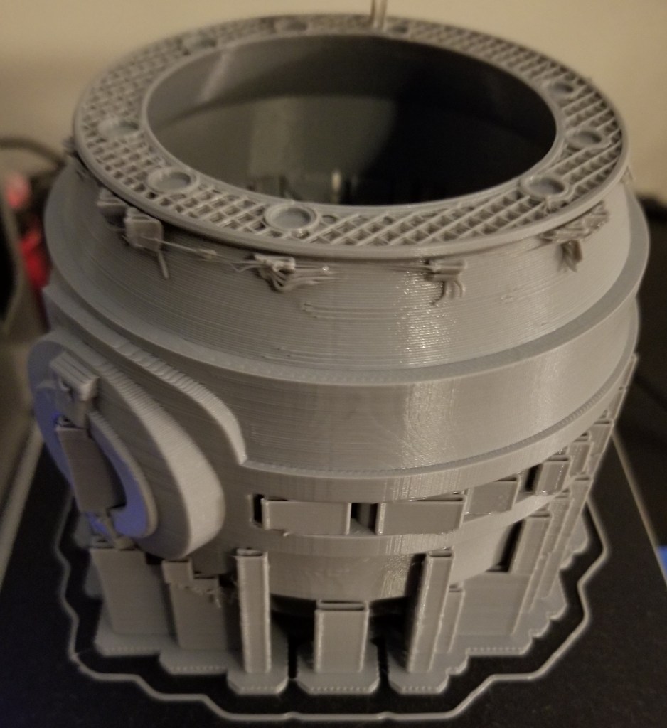
Failed print…. this is where I found out Octoprint doesn’t like 12+ hr prints
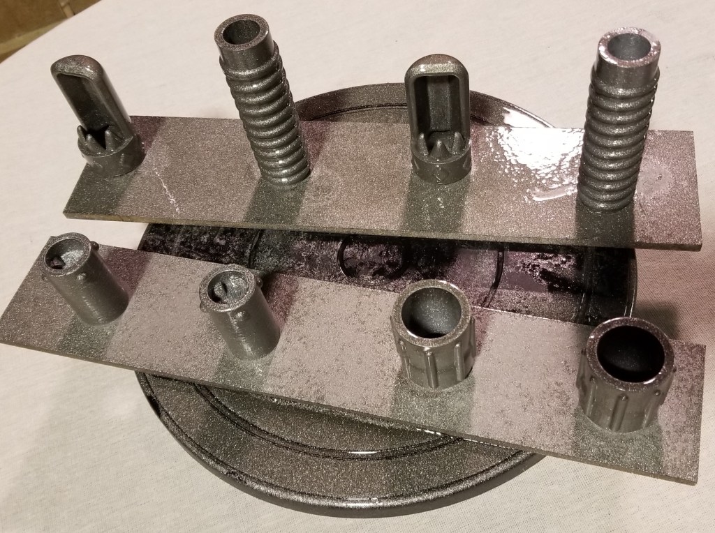
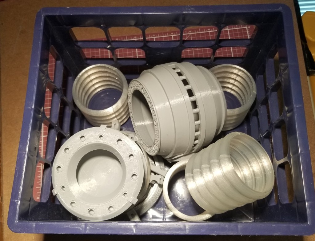
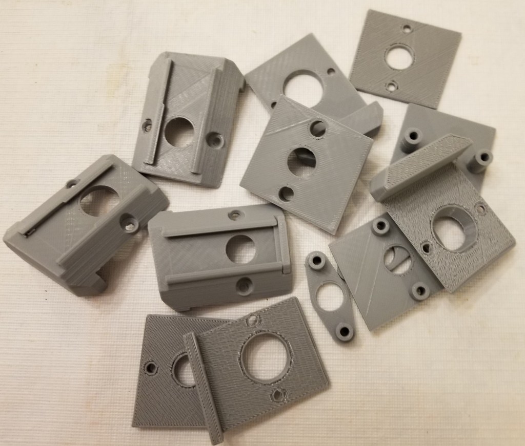
3D printed parts, before I took the time to reprint the failed reaction chamber.
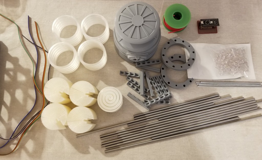
One of the nice things about this version is that most of the parts were broken into easier to print and clean up pieces. There was a bit of a tradeoff, though. It required coat hanger wire for some parts and replace others with stainless steel rods.
It was easy enough to buy the rods, and purchase and cut the steel coat hangers… but I was unable to cut the rods myself. I ended up supporting a local business and contacting my local machinist (who I’ve gone to before when there were metal parts I couldn’t fix or fab myself). It was kinda pricey… but precisely and cleanly cutting and finishing stainless steel is no joke, and this guy did an excellent job of it.
Unfortunately, I found out later that the lengths I have him did not precisely match what was needed for some of the 3D printed parts.
This led to a bit of experimentation with modifying the 3D models and reprinting the “tension members” to “cheat” them to a length that would work with the steel rods. That took a bit longer than it should have due to unexpected 3D printer problems.
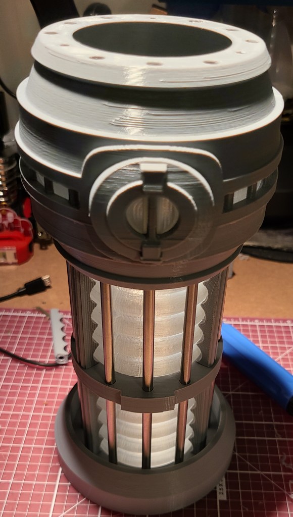
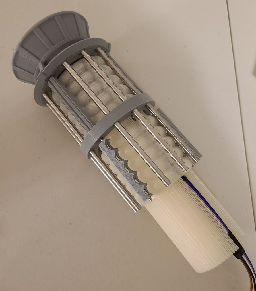
Test fitting success!
By the way, if you’re wondering where the coat hanger wires went, they are inside those gray pieces around the clear section, spaced between the steel rods.
Getting the lights in there and getting them to work took a bit, but I finally finished that recently. The system runs off of an Arduino Nano board, with a small board to break the wiring out. Before I get to the final stuff, I want to share a lessons learned.
If you use a breadboard of any kind… check how the the holes are connected! For some reason I thought this board left the holes unconnected and that I’d have to spread solder between components to form connections. Turns out they were connected and it hadn’t occurred to me to look at the back of the board until after I had soldered the resistors on. This is also why it is a good idea to buy spares of parts (or multi-packs) when working on a project. Otherwise it could cost you a lot of time and extra shipping.
Great access for wires, right?
D’OH!
A new board and a lot of soldering later, this is what I ended up using:
Ignore the putty, they were holding the connector pins on for soldering
I realized that this time on a project I didn’t want to trap myself with my directly soldering disparate wires to the board, so I added connector pins so I could have removable cables for disassembly/modification. I wasn’t gonna bet on getting it right the first time!
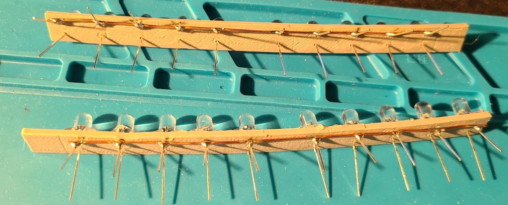
To keep the count of LEDs and wires down a bit, I used the diffusers someone else had designed (links at the bottom).
The circular indentations are where the LEDs go.
It uses a “light pipe” design to spread the light around in a mostly circular pattern. There was even a special one for the reaction chamber…but I ended up not using that.
Wiring the LEDs took a while, but it was more tedious than it was difficult. I think it was mainly because I took the time to plan out what I was doing before I started in more detail, rather than trying to wing it and label a bunch of wires afterwards.
Paper, colored pencils, and a straight-edge go a long way towards helping planning. I used this to make a simplified guide for wiring… but I cleaned up after finishing and don’t know where it currently is.
To avoid going insane with trying to glue in each LED and try to solder all the connections with reasonable spacing, I designed and printed spacers that I could simply stick the wires of the LEDs through. I think the wires would have held, but to make things simpler on myself (and so they wouldn’t push out during soldering) I hot glued them after putting them in.
Madness? THIS. IS. PLANNING!
To drastically cut down on the number of wires required, I soldered all of the negative terminals to a common grounding bus bar made from a bare copper wire.
10 wires enter, one wire leaves.
Referencing the drawings I had made earlier, I soldered some ribbon cable to the positive terminals, allowing me to have traceability through color-coding. The wiring is mirrored on the opposite side, so that each control output from the electronics board controls the lights in the mirrored position on top and bottom of the warp core lamp. This keeps the number of control pins needed down, and simplifies the coding.
Wire the rainbow… to save yourself headaches later.
These lights on the spacer bars fit snugly into the diffusers.
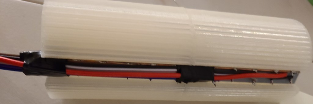
The top section. Easily identifiable by the big red grounding wire because I forgot to connect the grounding wire first. Also…snip your extra wire leg length to reduce problems.
As mentioned in the note above, I forgot to wire the ground wire first on the top section, meaning I had to add it in last, connecting it at the far end rather than the close end. In the bottom section I did it first, because I really needed room for the power/programming USB cable to fit in.
These segments then slid into the corrugated sections.
This was actually when I realized the grounding wire blunder. All positive and no negative wires.
An intermediate stage for no reason other than I like this picture.
Here’s how the wires connected up before the final closing of the casing.
Note the removable connectors for all the wires in case I needed to adjust anything. The colorcoding made connecting them to the board a breeze. The USB cable goes out the bottom for programming and power.
Now we get to where I kinda got angry. Here are the parts just before I was planning to connect the last couple wires and close it up.
Before I realized my planning failure.
Look at the circuitry. Look at the diffuser that’s supposed to go into the central reaction chamber. Now look at the reaction chamber. Do you see it yet?
THE DIFFUSER AND THE CIRCUIT DON’T BOTH FIT INTO THE CHAMBER AT THE SAME TIME.
I had planned for this somewhat with the board, but hadn’t fully taken into account the flexibility of the wires or the added height of the removable connectors.
Thankfully,
1) the diffuser isn’t 100% necessary (though the light would look better in that section
2) the diffuser was weak
3) RAL CAN CRUSH DIFFUSER WITH BARE HANDS AND EXTRACT LEDS INTACT
I kinda went barbarian on it in my desire to finish. I ripped the central diffuser apart, and just shove the LEDs in the compartment with the rest. Also, after a test fitting and plugging it in, I realized that the arduino had red LEDs that clashed with the color scheme, and put some electrical tape over them to get rid of the distracting red glow.
I closed the thing up… and then got to do something that still makes me chuckle a bit.
DRAMATIZATION OF ACTUAL EVENTS
I pulled out the rubber mallet and began gently tapping on the end of the warp core to make sure all the rods were seated as well as they could be.
After a bit of updating some code I wrote for this years ago (and cursing at two different computers for a few hours because they didn’t want to behave with uploading to the arduino) I finally got it turned on.
Engineering to bridge, the reactor is online!
I went through a few iterations of code and pseudocode (and had to remind myself that with this board the counting started at 2 rather than 0 or 1), and finally got it to a state I liked.
Here’s the initial light pattern I went with:
I’ve got an intermediate version of this one somewhere with an extra delay built in after the FOR loop because I didn’t like that the light jumped immediately from the bottom LED to the top again. It just seemed jarring.
Here’s what I’ve most recently decided to use:
This one has 2 or 3 “waves” at a time passing through each end to the center. It looks less like a jarringly looped GIF than some of the other iterations I went through.
I originally planned on plugging this into the raspberry pi that I control my 3D printers with, but apparently Octoprint gets confused by the extra USB connection, so I have it connected to a USB wall adapter for the moment. Though I have realized I can plug it into the USB adapter in my car as well…
I hope you all enjoyed this, and I’m glad to have finally finished this project after years of wanting to build this, and I was finally able to take this off my project board.
Reference Links For Construction:
Here’s the original I saw that inspired me years ago:
Now that I’ve submitted it as my entry for the 2020 Zero Day competition, I feel like I can share what I’ve been working on lately.
This may end up being the first in a series of “Standard Runner’s Constructs,” and the instructions are written as such, in an in-universe style. The idea is that runners are trying to make sure their future teammates are properly equipped and educated. If you “can’t find good help anymore,” sometimes you’ve gotta train your own.
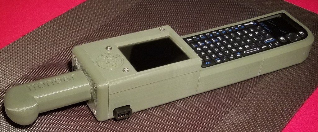
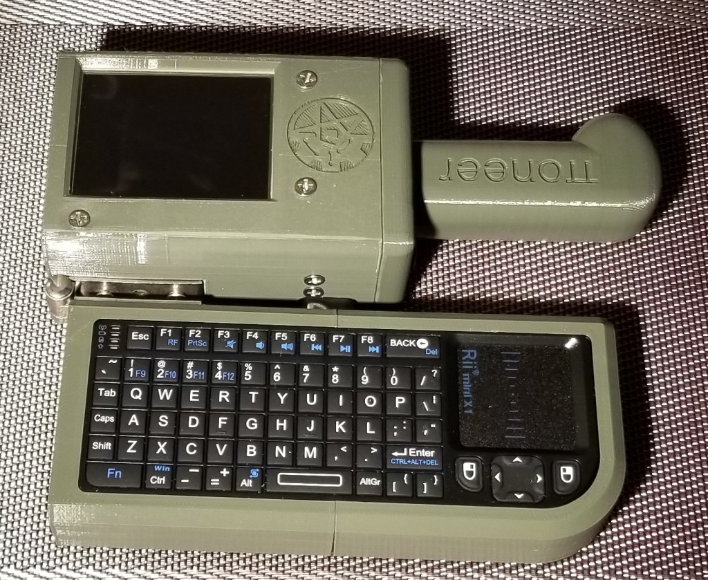
I present the 𝝅oneer Falchion, a pi zero w based micro cyberdeck (or microdeck).
Runner’s First Cyberblade, or a “Decker’s Sidearm”
The backside. Note the data-quillions, recessed power switch, and hinge.
Operating configuration.
Easy charging port.
I took inspiration in designing this from the Austro-Hungarian M1853 Pioneer’s Falchion. I had gotten the first inkling of an idea of a blade shape from the shape of the keyboard, and then went poking and asking around to find a blade with a somewhat similar shape. That’s what informed the shape of the hilt and the placement of the quillions in particular.
The features include a micro-USB charging port on the hilt end, two USB-A “data-quillions”, a touchscreen display, and a wireless keyboard that folds on a hinge along the back of the “blade” into the operating position under the display. The power switch is accessible through a hole on the backside of the device.
I designed and built it for the competition hosted here:
The gist of it is that we are holding a mini virtual maker faire, with a competition portion. The competition requires using a Raspberry Pi Zero (or Zero W for the wireless version) as the core of a cyberdeck that we designed in a limited amount of time, with a limited number and volume of 3D printed components, and including the required models and instructions as our entry.
The winner gets their design printed in resin and shipped to them.
As part of the competition I had to submit the 3D models and instructions, but I also have them hosted here:
I got fed up with the power cables sticking out of the side of the case, so I decided to make the power switch a more integral part of the build. Also, I didn’t like the gaping hole in the case.
There were two power switches, one for the deck itself, and one for powering the USB hub. I modified this one for the hub, deciding to route it fully inside the case, even though that means I have to briefly open the tray to turn on the hub.
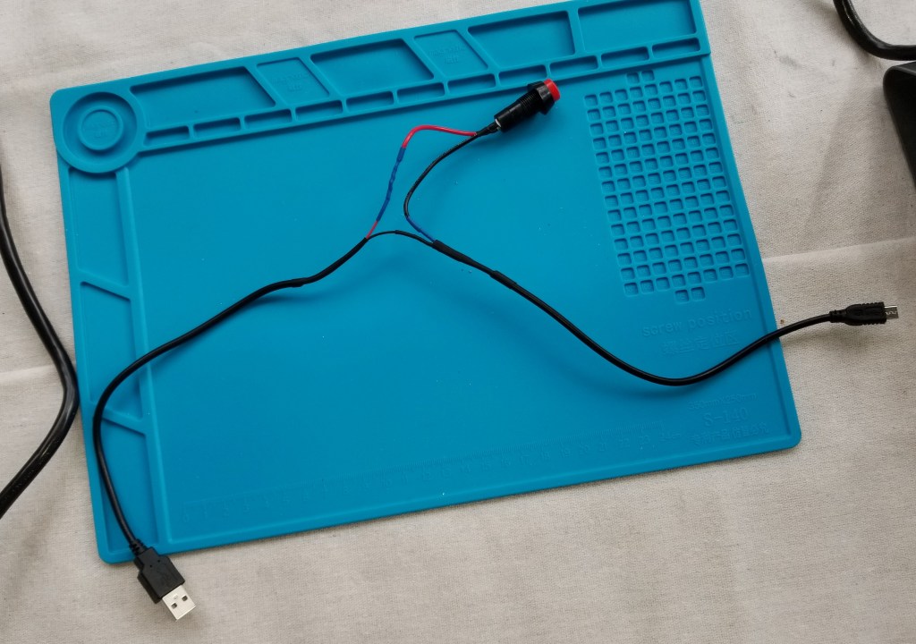
I also made this cable up for the main power to the Pi.
As part of this design process there was a lot of tinkering and iterating.
And, I mean a LOT of tinkering. This is what I ended up with:
I knew I liked the idea of a red safety cover for the switch, but those are designed to turn a regular flip switch off when they closed. I needed a way to have a cover a switch while the thing was still powered on. I found the switch that would fit through the hole of the safety cover (after a little… modification with the deburring tool), and figured out how to design the little bugger to hole the actual switch, the switch cover, allow for proper free movement of the switch to function, and attach the switch neatly and securely to the case. I’ll spare you the iterations, but it took a while, and I think I got it to look pretty good and hold well. I like that I have a red power button under a red safety cover now. It just feels… right.
I’ve been wanting to build one of these for years, since before I got my first 3D printer, but I had so many problems with my 3D printers on long prints that I never got around to it.
Well, I’m fixing that now!
For one thing, the models for this have been redone drastically, increasing quality and reducing the print time.
It’s also been downsized slightly, which makes the large parts fit on my smaller 3D printer.
For another, I’ve been fixing my 3D printers, and have had all this monitored print time available recently, so I’ve had no excuse NOT to make it anymore. So, I’ve been spitting out the parts for this thing lately.
Those translucent sections were much larger and more complex in the original model, each made of 5 toroids. Also, many pieces were replaced with metal rods that I was able to order on Amazon, I just have to cut them down to the correct length.
So… yet another project ongoing! I’ve gotten the tools and hopefully all the parts I need, so when I have some more time (I’ve been kinda busy) I’ll be:
Writing the arduino code for controlling it
Testing the code on a breadboard
Soldering an absurd number of connections
Cutting a bunch of metal rods with a reciprocating saw
And for a random yet practical use of 3D printing: S-hooks for hanging tools up. I needed to get my saws out of the way, and I realized I had a place to hang them up… as long as I had something to hang them up with. S-hooks seemed like what I needed, so I did a quick search and printed a couple out. Now the saws are (reasonably) safely stored out of the way.
There were a lot of maintenance items that I ended up trying/doing, and I don’t feel like dragging this out any further, so I’m trying to condense the rest of what I did here.
Smooth Motion Maintenance:
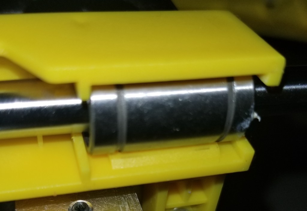
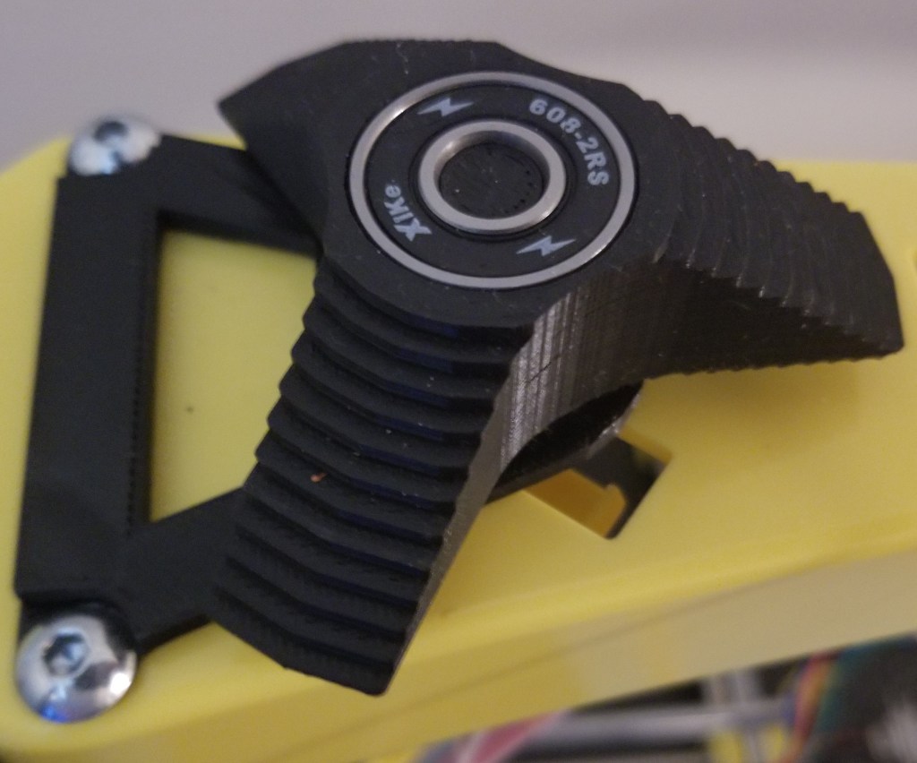
This is a combination of some general maintenance items. I replaced all the bearings I was able to. This included the ones on the hot end carriage and on the vertical axis, but I had no way to easily swap out the ones on the print bed carriage.
While I’m thinking about it, remember that if you have to swap out bearings, put the thicker white lithium grease on the inside of the new bearing before putting it on the rod, to make sure the bearing gets fully lubricated. When you’ve finished assembling, make sure to move the bearings back and forth several times to make sure the lubrication spreads within the bearing evenly.
While doing that, I cleaned and lubricated all the linear rods and z-axis screws. I also replaced all the timing belts. I think this has reduced the friction greatly, and improved the smoothness/ease of motion.
Here’s one of the bearings I replaced on the extruder carriage.
Stepped Spool Holder:
As I discovered in the previous post in this series, the smooth spool holder allowed the spools to slide off, and I remembered that there was a stepped variant. I printed off one of those, assembled it… and it works much better! The steps keep the spools on top of the printer, despite the vibrations from the printer’s motion in certain circumstances.
This spool holder allows for quicker filament changes, without having to fiddle with an exterior spool holder. This is especially helpful as the original spool holder had required disassembling the holder each time I wanted to change filaments, and clamping to keep it from moving in the way of the print bed.
Hot End Replacement:
I was having some temperature fluctuations on the hot end, at least in what temperatures were registering. I’m so glad I started using Octoprint and could monitor temperature telemetry!
Based on talking with other people about it, and looking at the symptoms, it appeared to be something wrong with the thermistor and/or the wire connecting it to the control board. I was considering replacing the thermistor, but I was having difficulty finding a compatible one. I was, however, able to find a replacement hot end from the manufacturer, which would give me the added benefit of replacing the nozzle and lining tube at the same time, so I swapped out the whole assembly.
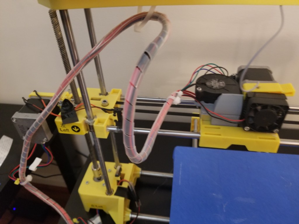
It was a straight up swap for identical parts, though it was tedious because of the cable wrapping that had to be removed in order to remove the old wires and include the new ones.
This stuff is necessary to reduce wear on the wires, but annoying to implement.
Cooling Fan Addition:
The major issue I was seeing with overhangs and general print quality was an overheating issue. There are a couple ways to address aspects of this: adding a silicone sock to reduce reheating issues, and/or adding a cooling fan to make the top surfaces cool more quickly. For now I’ve only implemented the latter option. I’ve been unable to find a compatible silicone sock so far.
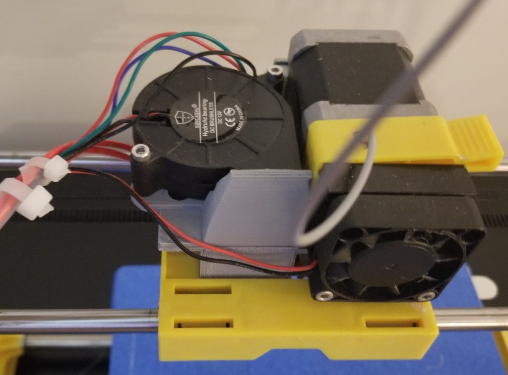
thedayowl on Thingiverse designed a fan duct for a blower fan to be added to the carriage. You can find it here. I printed it out, ordered the other parts, and attached it to the assembly.
The trickiest bit was figuring out how I was supposed to connect the power. There’s an open connection on the board that provides sufficient power continuously. You can’t control it through the software, but I don’t see the harm in letting that small blower run continuously.
By the way, the connector on the board is NOT the standard connector it looks like, and I’m not sure what it is, so I made do with a dupont connector.
Gear Grinding/Nozzle Turnoff/Layer Shift
There was an intermittent issue that I’ve had with the stepper motors (particularly on the y axis, but occasionally on the x axis) moving unexpectedly, often running into the end stop and grinding the belt. When that happened, the hot end would turn off (causing the filament to stop flowing and just grind), and the printer would lose track of the hot end’s location (causing massive layer shifts), both of which ruined the print. I attacked this from a few different angles. Replacing the belts earlier in the process was part of one of the attempts, as I’ve had issues with slippage before, as well as just part of replacing older parts.
Stepper Motor Driver Tweaking:
Based on a recommendation I’ve gotten from some other people, I got a multimeter to check the stepper motor drivers, and a ceramic screwdriver to adjust the voltage. I’ve tried tweaking it a few times, but I didn’t really see any improvement.
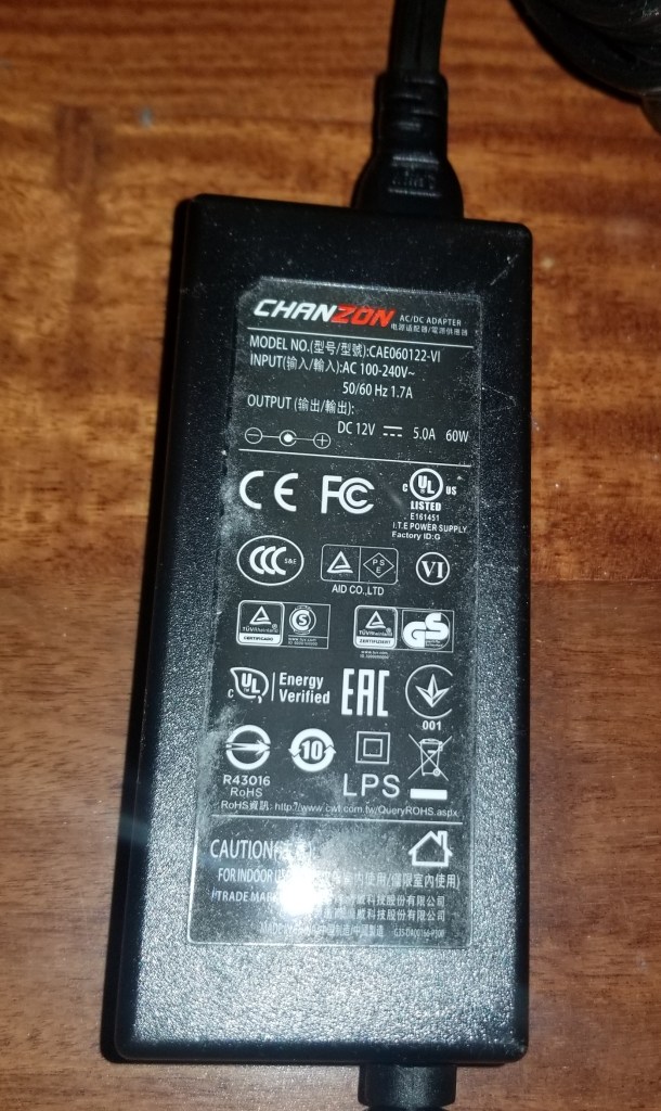
Power Supply Replacement:
Upon other recommendations, I decided to try getting a replacement power supply. I’ve been told that the one that came with the printer is considered a really reliable brand, but since I’ve swapped out the power supply the printer seems to have stopped having that intermittent failure.
Finished
With all that finished… WOW. This older printer can now print better than my newer one! I now do all my more precise prints on this printer.
For a point of comparison, here’s the before photo of the temperature towers printed on this printer.
Absolute rubbish!
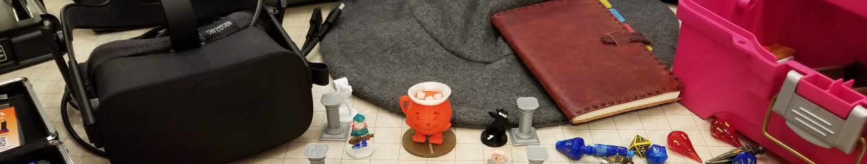
And here’s the miniatures that I’m able to print now! I’ve been running it a lot lately building up my miniatures collection.
Thoughts/notes for the future:
If I run into issues on the hotend again, I think I may do what I’ve seen others do and switch to a more industry standard hotend, though that’d be an… interesting conversion process. It would make finding replacement parts a lot easier, though!
I think there is a little bit of a bed level issue, still, and I’m not sure how much is in the tramming and how much is in the metal bed I placed on it. It may be related to how I mounted the bed with command strips.
For now I’m printing mostly small items. When I print larger items I get a bit of warping, so I think I need to remember to implement brims on the larger ones. I’m not sure how much is due to the unheated bed, and how much from variations in leveling. And no, I’m not considering adding a heated bed anytime soon. From what I’ve read, trying to do a DIY heated bed increases the fire risk more than I am comfortable with.
At one point I was considering replacing the z-axis screws with thicker ones, but the manufacturer used a nonstandard interface piece (it had 3 holes instead of the standard 4), so I couldn’t easily swap them out without also having to print and install completely new blocks at the ends. This is the kind of nonsense that makes me want to scratch build a printer on my own down the line, with an eye for maintenance and using industry standard parts.
Anyway, I guess I’ve got to start working on the other printer soon to bring up the quality level on it! It feels kinda weird that my older and larger printer is currently better at producing the smaller miniatures. I need to address this imbalance, so I can print smaller things on the smaller printer and larger things on the larger printer.
I decided that I wanted to be able to display and easily access my collection of D&D miniatures. I came across a concept for reusing empty filament spools. Their version had faceplates, but for the moment I just want to at least get this thing functional. I stacked my empty spools, and connected them with some tacky material.
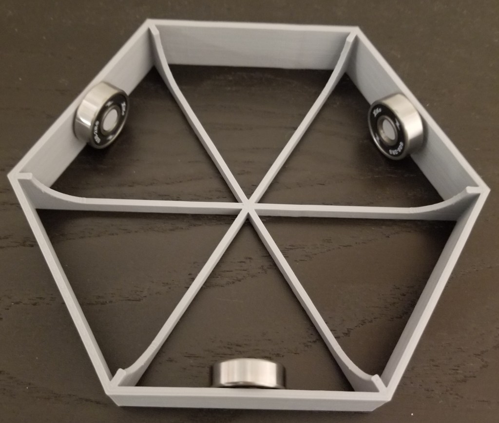
It’s convenient, showing off my minis for ease of access… but the back half is hard to see and reach. This is where the turntable comes in. I had tried one version where it was a plate sitting on a single skateboard bearing, but that was too brittle and the whole thing wobbled (the spools make it top-heavy). So, I switched to this design:
You can find the original turntable design on Thingiverse here:
I didn’t need the top plate, seeing as the bottom spool provides a surface to rotate on, but the bottom plate does provide a much more stable base to rotate the entire tower on.
I may end up upgrading the tower to have the nice stonework facings here, but so far I don’t want to give up the printer runtime for it. It was the inspiration for this project, though.
At any rate, I now have a way of seeing what minis I have, instead of having to dig through plastic containers. Maybe post-quarantine I can use it for hosting some RPGs.